
Novel oscillating cylinder mechanism for hydraulic motor

A hydraulic motor, a new type of technology, applied in the field of hydraulic motors, can solve the problems that the position of the roller cannot be fixed all the time, the wear of the trunnion and the end cover, and the increase of the speed, so as to prevent the phenomenon of seizure, prolong the life of the parts, and improve the starting torque Effect

Pending Publication Date: 2020-08-11
NINGBO XINHONG HYDRAULIC
View PDF0 Cites 0 Cited by
  • Summary
  • Abstract
  • Description
  • Claims
  • Application Information

AI Technical Summary

Problems solved by technology

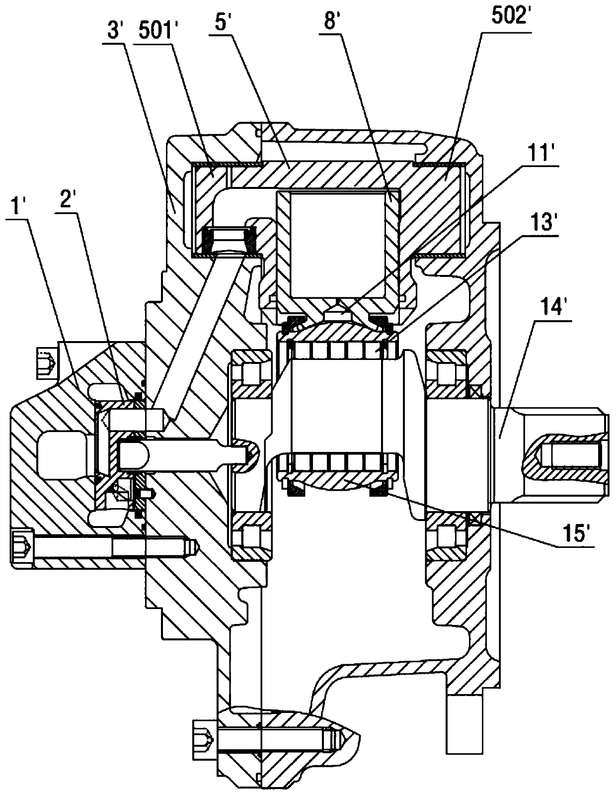
The left and right trunnions (501' and 502') are respectively arranged on both sides of the swing cylinder 5' to connect the oil inlet structure. If the concentricity of the left and right trunnions of the swing cylinder with this structure cannot be done well, the swing cylinder When the rotating speed of the body is high, it will cause serious wear between the trunnion and the end cover 3', thus limiting the increase of its rotating speed
In addition, due to the gaps between the rollers of the radial roller bearing 13', the positions of the rollers cannot be fixed all the time, which will also limit the increase of the rotational speed and cause wear and heat at the same time.

Method used


Image

  • Novel oscillating cylinder mechanism for hydraulic motor
  • Novel oscillating cylinder mechanism for hydraulic motor
  • Novel oscillating cylinder mechanism for hydraulic motor

Examples


Embodiment

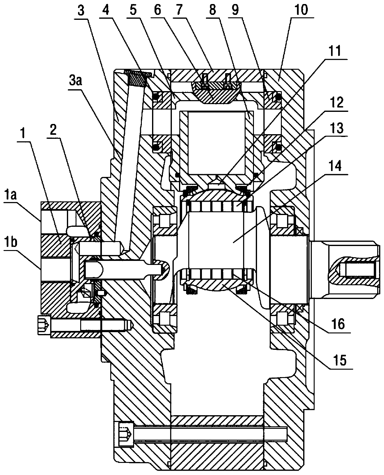
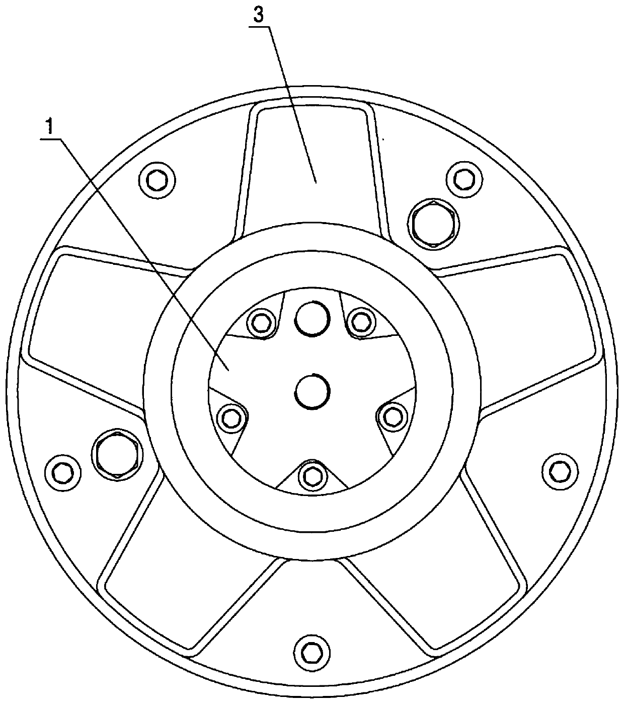
[0024] see Figure 2 to Figure 8 , a new type of swing cylinder mechanism for a hydraulic motor according to an embodiment of the present invention includes: an oil pan 1, an oil distribution mechanism 2, a rear cover 3, a swing cylinder body 5, a plunger 8, a housing 10, a transition sleeve 7, a static pressure Bearing 11, radial roller bearing 13, spherical plunger support ring 15, plunger clamping ring 12 and crankshaft 14; first oil inlet passage 1a and second oil inlet passage 1b are arranged on the oil passage 1 along the axial direction, The rear cover 3 is provided with an inclined hole 3a communicating with the first oil inlet passage 1a and the second oil inlet passage 1b, and the high-pressure oil passes through the oil pan 1, passes through the distribution mechanism 2, the inclined hole 3a of the rear cover 3, and then passes to the swing cylinder body 5, and transmitted to the plunger 8, the swing cylinder 5 and the plunger 8 are always in a centered state throug...


PUM


Abstract

The invention discloses a novel oscillating cylinder mechanism for a hydraulic motor. High-pressure oil passes through inclined holes of an oil through disc (1), a flow distribution mechanism (2) anda rear cover (3) to the interior of an oscillating cylinder body (5) and is transmitted to a plunger (8); the oscillating cylinder body (5) and the plunger (8) are always in a centering state througha static pressure bearing (11) and a spherical plunger supporting ring (15); the rear end of the oscillating cylinder body (5) can rotate around a spherical hinge (6), and the spherical hinge (6) is fixed on a transition sleeve (7); the left end and right end of the oscillating cylinder body (5) are respectively in contact connection with a wear-resistant floating ring (9), and an ideal static pressure sealing effect of the oscillating cylinder body (5) and each wear-resistant floating ring (9) is achieved through a floating sealing assembly (4); and the high-pressure oil is transmitted to a crankshaft (14) through the static pressure bearing (11) and a radial roller bearing (13), so that power output is realized. Through the arrangement, the novel oscillating cylinder mechanism for the hydraulic motor has the advantages of high rotating speed, high pressure bearing capacity, high power, low abrasion and the like.

Description

technical field [0001] The invention relates to the technical field of hydraulic motors, in particular to a novel swing cylinder mechanism for hydraulic motors. Background technique [0002] The hydraulic motor is an actuator of the hydraulic system, which converts the hydraulic pressure energy provided by the hydraulic pump into the mechanical energy (torque and speed) of its output shaft. It is widely used in injection molding machinery, ships, hoists, engineering machinery, construction machinery, coal mining machinery, mining machinery, metallurgical machinery, ship machinery, petrochemical, port machinery and other fields. [0003] The power of the hydraulic motor mainly depends on the pressure of the motor, the displacement of the motor and the actual output speed (power = pressure of the motor * displacement of the motor * speed of the motor / 60). The size of the hydraulic motor has limited its displacement. Existing high-torque hydraulic motors are mostly low-speed...

Claims


Application Information

Patent Timeline
Patent Type & Authority Applications(China)
IPC IPC(8): F03C1/053F03C1/04F03C1/28F03C1/32F03C1/38
CPCF03C1/053F03C1/0403F03C1/0406F03C1/0415F03C1/0444
Inventor 吴英华周小宝戎正林王迪赵广齐周丹苏经川
Owner NINGBO XINHONG HYDRAULIC
Learn More