Waste heat recovery system of air compressor

A waste heat recovery system and air compressor technology, applied in heating systems, space heating and ventilation, heating methods, etc., can solve problems such as energy waste, improve operating conditions, reduce maintenance costs, and reduce machine failures.

Pending Publication Date: 2020-08-11
SHANDONG HUAYU PRESSURE VESSEL
View PDF0 Cites 0 Cited by
  • Summary
  • Abstract
  • Description
  • Claims
  • Application Information

AI Technical Summary

Problems solved by technology

The energy consumed by compression heat accounts for about 80% of the operating power of the unit. Usually, this part of energy is exchanged into the atmosphere through the air-cooled or water-cooled system of the unit, resulting in a waste of energy

Method used


Image

  • Waste heat recovery system of air compressor

Examples


Embodiment Construction

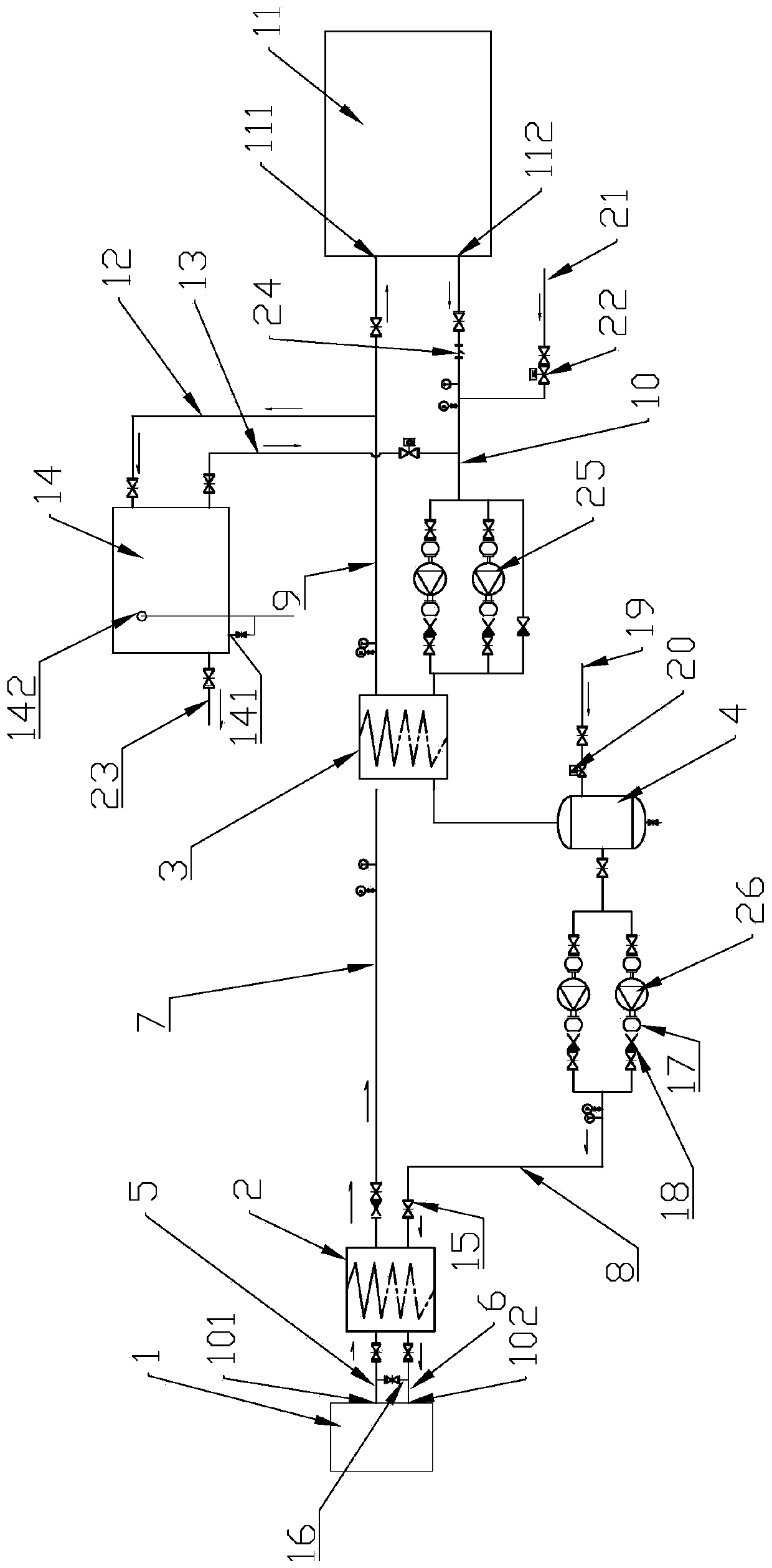
[0017] Refer to the attached figure 1 The air compressor waste heat recovery system of the present invention will be described in detail below.

[0018] The air compressor waste heat recovery system of the present invention comprises an air compressor 1, a first plate heat exchanger 2, a second plate heat exchanger 3, and a buffer tank 4, and the first plate heat exchanger 2 passes through the first pipeline 5. The second pipeline 6 is connected to the oil outlet 101 and the oil return port 102 of the air compressor 1, and is connected to the second plate heat exchanger 3 through the third pipeline 7 and the fourth pipeline 8. The first pipeline 5 communicates with the second pipeline 6, the third pipeline 7 communicates with the fourth pipeline 8, the buffer tank 4 is arranged on the fourth pipeline 8, the second plate heat exchanger 3 passes through the fifth pipeline 9, the sixth The pipeline 10 is connected to the water supply port 111 and the water return port 112 of the...


PUM


Abstract

The invention discloses a waste heat recovery system of an air compressor and belongs to wasteheat recovery systems. The waste heat recovery system structurally comprises the air compressor, a first plate type heat exchanger, a second plate type heat exchanger and a buffer tank. The first plate type heat exchanger is connected to the air compressor through a first pipeline and a second pipeline and is connected to the second plate type heat exchanger through a third pipeline and a fourth pipeline, the first pipeline communicates to the second pipeline, the third pipeline communicates to the fourth pipeline, the buffer tank is arranged on the fourth pipeline, the second plate type heat exchanger is connected to a heating unit through a fifth pipeline and a sixth pipeline, the fifth pipelinecommunicates to the sixth pipeline, and water tanks are arranged in parallel on the fifth pipeline and the sixth pipeline through a seventh pipeline and an eighth pipeline. The waste heat recovery system of the air compressor recovers heat, makes full use of the wasteheat and turns the waste into wealth, so that the energy sources are saved and the cost is saved. Meanwhile, the operating temperature of the air compressor is reduced effectively, the effective operation of the air compressor is improved, and the gas output of the air compressor is improved.

Description

technical field [0001] The invention relates to a waste heat recovery system, in particular to a waste heat recovery system of an air compressor. Background technique [0002] Today, when the world's energy is becoming more and more tense, the issue of energy saving and energy recovery has been put on the important agenda. Production facilities are constantly looking for potential energy savings. The energy recovery of compressors is one of the energy-saving measures to improve efficiency. The energy consumed by compression heat accounts for about 80% of the operating power of the unit. Usually, this part of energy is exchanged into the atmosphere through the air-cooled or water-cooled system of the unit, resulting in a waste of energy. Contents of the invention [0003] The technical task of the present invention is to provide an air compressor waste heat recovery system for the above-mentioned deficiencies in the prior art. The air compressor waste heat recovery system h...

Claims


Application Information

Patent Timeline
IPC IPC(8): F04B39/06F28D9/00F24D15/00
CPCF04B39/06F24D15/00F28D9/00
Inventor 朱令凯焦竞男李晶朱继兴
Owner SHANDONG HUAYU PRESSURE VESSEL
Why Eureka
Try Eureka