Rotary detonation combustion chamber capable of realizing observation of flow field structure of isolation section

A technology of combustion chamber and isolation section, which is applied in the direction of combustion chamber, continuous combustion chamber, combustion method, etc., to achieve the effect of stable airflow state

Inactive Publication Date: 2020-08-11
CHINA AERODYNAMICS RES & DEV CENT
View PDF5 Cites 2 Cited by
  • Summary
  • Abstract
  • Description
  • Claims
  • Application Information

AI Technical Summary

Problems solved by technology

It is very important to study the wave system structure in the isolation section, but there is no effective method to realize the direct observation of the wave system structure in the isolation section of the rotating detonation engine

Method used


Image

  • Rotary detonation combustion chamber capable of realizing observation of flow field structure of isolation section
  • Rotary detonation combustion chamber capable of realizing observation of flow field structure of isolation section
  • Rotary detonation combustion chamber capable of realizing observation of flow field structure of isolation section

Examples


Embodiment 1

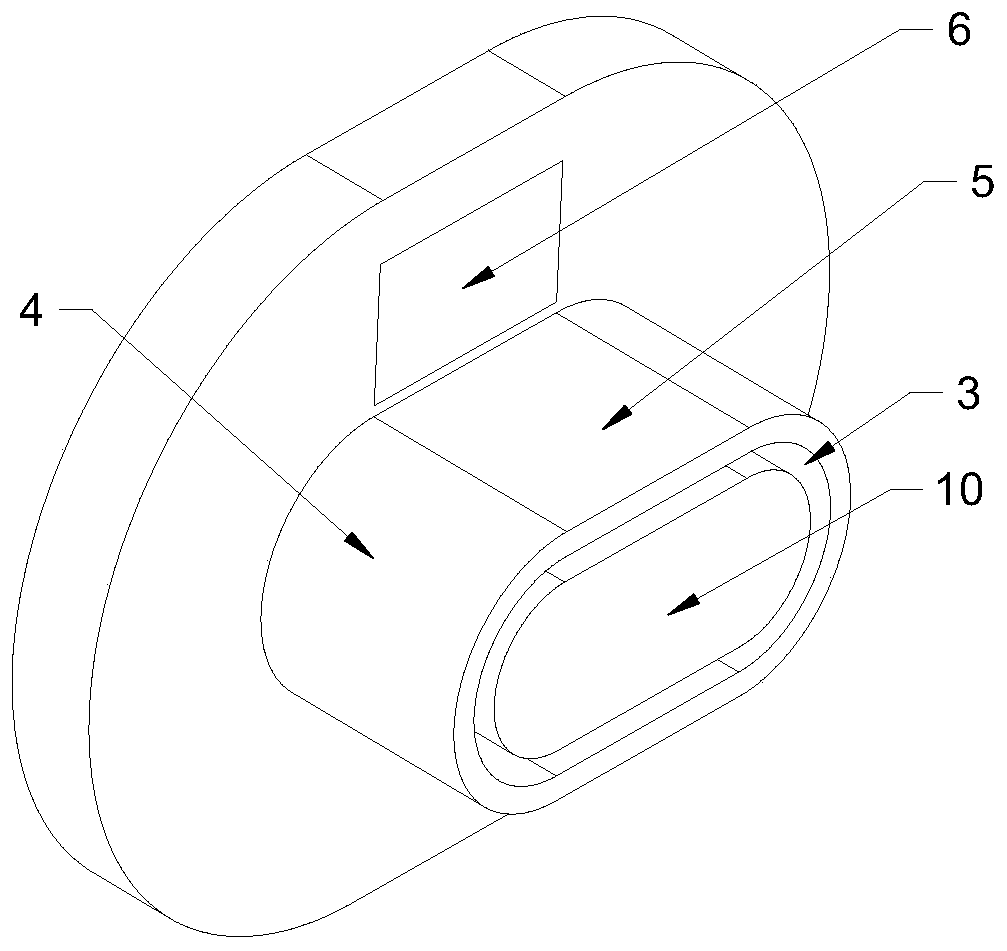
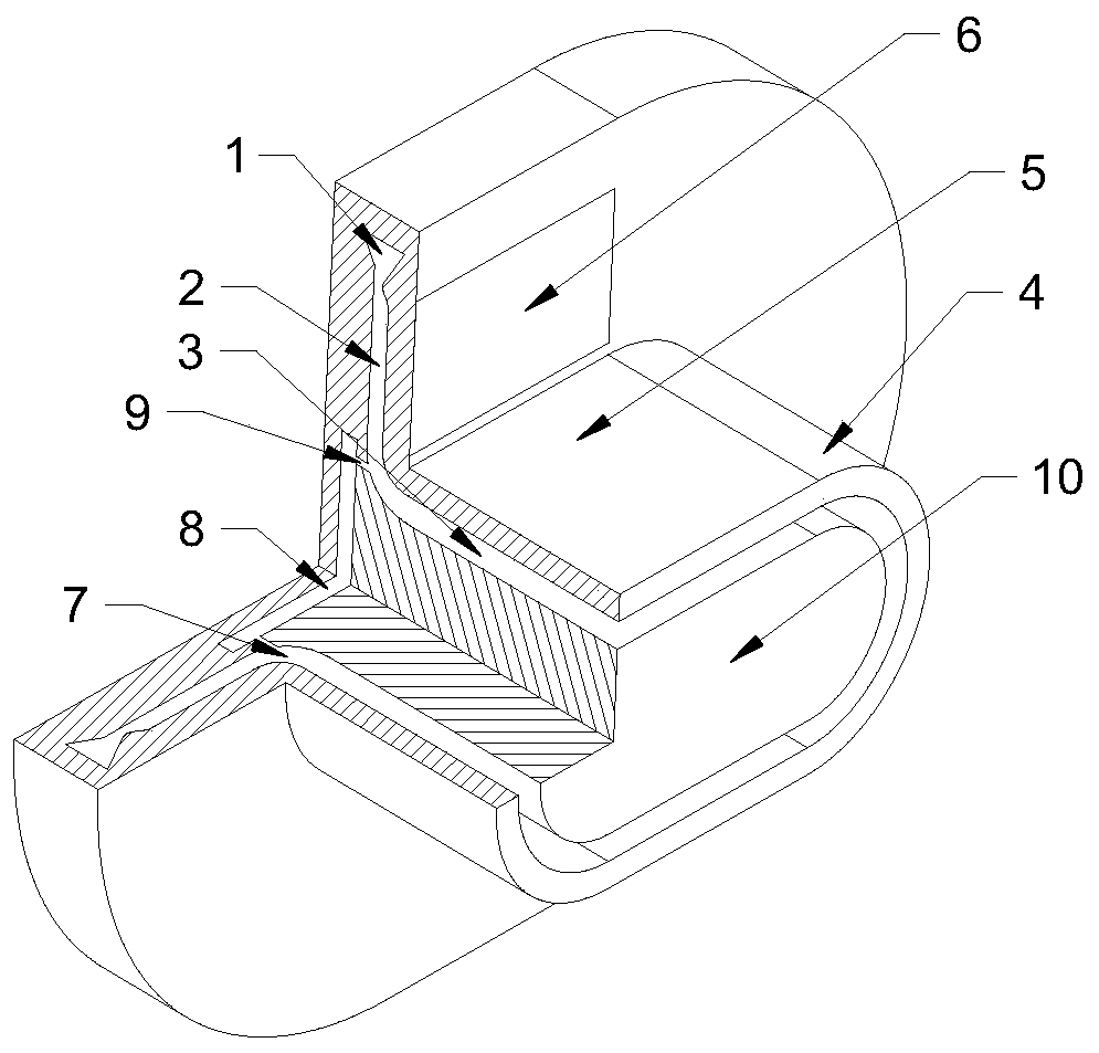
[0023] see figure 1 , figure 2 with Figure 7 , a rotary detonation combustor that can realize the observation of the flow field structure in the isolation section, mainly composed of a rotary detonation combustor 3 and an intake air mixing module arranged at the inlet end of the rotary detonation combustion chamber 3, the intake air mixing module and The central axis of the rotary detonation combustion chamber 3 is vertical; the cross section of the rotary detonation combustion chamber 3 is mainly a runway formed by two opposite semicircular parts 4 and a racetrack-shaped equal straight section 5 connecting the two semicircular parts 4 type structure; the intake mixing module is a hollow interlayer structure, including a radial raceway-type intake section 1, a radial raceway-type isolation section 2 and a fuel injection module located on the same central axis as the rotating detonation combustion chamber 3; The outlet end of the racetrack-type isolation section 2 communica...

Embodiment 2

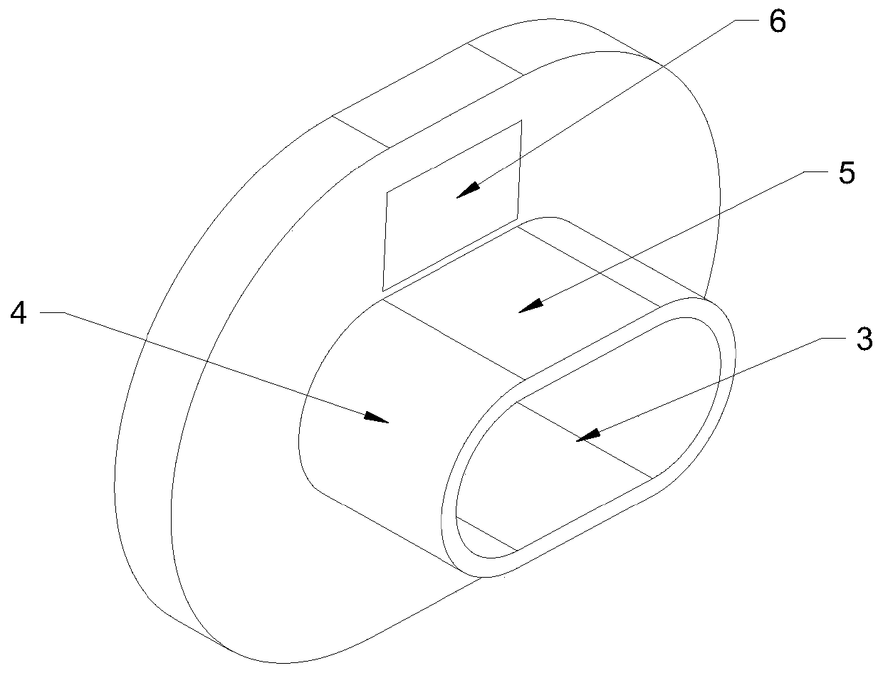
[0029] see Figure 5 , Image 6 with Figure 7 , a rotary detonation combustor that can realize the observation of the flow field structure in the isolation section, mainly composed of a rotary detonation combustor 3 and an intake air mixing module arranged at the inlet end of the rotary detonation combustion chamber 3, the intake air mixing module and The central axis of the rotary detonation combustion chamber 3 is vertical; the cross section of the rotary detonation combustion chamber 3 is mainly a runway formed by two opposite semicircular parts 4 and a racetrack-shaped equal straight section 5 connecting the two semicircular parts 4 type structure; the intake mixing module is a hollow interlayer structure, including a radial raceway-type intake section 1, a radial raceway-type isolation section 2 and a fuel injection module located on the same central axis as the rotating detonation combustion chamber 3; The outlet end of the racetrack-type isolation section 2 communica...


PUM


Abstract

The invention relates to the technical field of engines, and discloses a rotary detonation combustion chamber capable of realizing observation of a flow field structure of an isolation section. The rotary detonation combustion chamber mainly comprises a rotary detonation combustion chamber body and an air inlet mixing module, and the air inlet mixing module is of a hollow interlayer structure andcomprises a radial runway type air inlet section, a radial runway type isolation section and a fuel injection module; incoming air is accelerated by a supersonic nozzle of the radial runway type air inlet section to form supersonic airflow, and the supersonic airflow enters the radial runway type isolation section and is mixed with fuel to form combustible gas; and the high-speed combustible gas is detonated in the combustion chamber body to form high-frequency high-pressure rotary detonation waves, and the high-frequency high-pressure rotary detonation waves disturb the incoming flow to forma shock wave structure which is transmitted forwards to the radial runway type isolation section. Optical glass is arranged on the two sides of a radial runway type isolation section runner, corresponding optical observation equipment is arranged on the two sides of the optical glass, an observation light path passes through an isolation section flow field through the optical glass, and thereforeoptical observation of an isolation section flow field wave system structure is achieved.

Description

technical field [0001] The invention relates to the technical field of engines, in particular to a rotating detonation combustion chamber capable of observing the flow field structure of an isolation section. Background technique [0002] In a rotating detonation engine, the rotating detonation wave propagates at a high speed in the combustion chamber, with a frequency of several thousand Hz and a peak value of several MPa, and there are significant differences in the pressure of the combustion chamber along the circumferential direction, forming a high-frequency periodic pulsating pressure. This complex and harsh combustion backpressure environment will affect the injection and mixing process of fuel and oxidant. For the rotary detonation ramjet engine, this may directly affect the flow process at the inlet of the rotary detonation combustion chamber, and in severe cases, it will cause the intake port to be blocked and cause no start. For rotating detonation rocket engines...

Claims


Application Information

Patent Timeline
IPC IPC(8): F23R3/52
CPCF23R3/52
Inventor 王超郑榆山蔡建华刘彧肖保国白菡尘邢建文何粲晏至辉
Owner CHINA AERODYNAMICS RES & DEV CENT
Why Eureka
Try Eureka