
Chip heat dissipation device and method

A chip heat dissipation, chip technology, applied in the field of communication, can solve the problems of reducing product reliability, high cost of immersion system, increasing product design complexity, etc., to achieve the effect of compensating for the performance degradation of heat pipes and improving heat dissipation efficiency

Inactive Publication Date: 2020-08-11
BEIJING XINWANG RUIJIE NETWORK TECH CO LTD
View PDF0 Cites 0 Cited by
  • Summary
  • Abstract
  • Description
  • Claims
  • Application Information

AI Technical Summary

Problems solved by technology

[0008] Immersing the entire product in the liquid to achieve heat dissipation, the cost of the entire immersion system is high, and in order to solve the problem of product corrosion resistance, it will also increase the complexity of product design and reduce product reliability, which cannot be accepted by data center customers

Method used


Image

  • Chip heat dissipation device and method
  • Chip heat dissipation device and method
  • Chip heat dissipation device and method

Examples


Embodiment Construction

[0048] In order to make the objectives, technical solutions, and advantages of the embodiments of the present invention clearer, the technical solutions in the embodiments of the present invention will be described clearly and completely in conjunction with the accompanying drawings in the embodiments of the present invention. Obviously, the described embodiments It is a part of the embodiments of the present invention, not all the embodiments. Based on the embodiments of the present invention, all other embodiments obtained by those of ordinary skill in the art without creative work shall fall within the protection scope of the present invention.

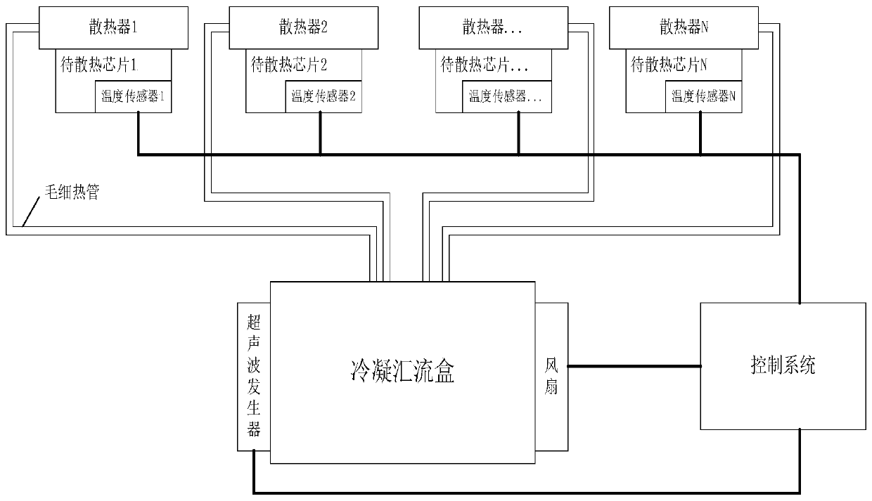
[0049] figure 1 Is a schematic structural diagram of a chip heat dissipation device provided by an embodiment of the present invention, such as figure 1 As shown, the device includes: at least one radiator, at least one capillary heat pipe, a condensation junction box, and an ultrasonic generator;

[0050] The radiator 1 to the radiator...


PUM


Abstract

The invention provides a chip heat dissipation device and method. The device comprises at least one radiator, at least one capillary heat pipe, a condensation confluence box and an ultrasonic generator. The radiator is in contact with the surface of a chip to be cooled through a heat conduction interface material and used for absorbing heat emitted by the chip to be cooled and vaporizing liquid inthe radiator through the heat. The capillary heat pipe is communicated with the interior of the radiator, is communicated with the interior of the condensation confluence box and is used for feedinggas generated after the liquid is vaporized into the condensation confluence box. The condensation confluence box is used for liquefying the vaporized gas in a centralized manner, enabling liquid generated after liquefaction to flow back to the radiator through the capillary heat pipe, and cooling the chip to be cooled through mutual change of gas-liquid states of the liquid. The ultrasonic generator is arranged outside the condensation confluence box and used for accelerating the backflow speed of liquid in the condensation confluence box along with the capillary structure through ultrasonicvibration. The problem that the performance of the heat pipe is reduced due to deformation of the capillary structure is solved, and the heat dissipation efficiency is improved.

Description

Technical field [0001] The embodiment of the present invention relates to the field of communication technology, and in particular to a chip heat dissipation device and method. Background technique [0002] With the rise of 5G technology, the port bandwidth and density of data center switches are getting bigger and bigger, which brings more and more challenges to the heat dissipation design of switch products. In order to improve the utilization rate and port density of the data center, and reduce the capital investment, each card of a single switch is required to be controlled at the height of 1U and the maximum depth of 1200mm of the 19-inch standard cabinet. In addition, the heat generated by the main chips in the data center accounts for the heat generated by the switch. More than 70% of the high-power chips that support 400Gps port rates in data center products have reached a thermal power level of more than 400 watts. Therefore, the development of a new type of heat dissip...

Claims


Application Information

Patent Timeline
Patent Type & Authority Applications(China)
IPC IPC(8): H01L23/427H01L23/473
CPCH01L23/427H01L23/473
Inventor 刘贤兵
Owner BEIJING XINWANG RUIJIE NETWORK TECH CO LTD
Learn More