Protection device for hemodynamic monitoring

A hemodynamics and protection device technology, applied in the field of hemodynamics monitoring protection devices, can solve the problems of no guide structure and complex positioning, and achieve the effect of convenient clamping operation, reliable positioning and reliable protection function

Pending Publication Date: 2020-08-14
THE SECOND XIANGYA HOSPITAL OF CENT SOUTH UNIV
View PDF1 Cites 0 Cited by
  • Summary
  • Abstract
  • Description
  • Claims
  • Application Information

AI Technical Summary

Problems solved by technology

However, the above structure does not have a guiding structure, and the positioning is complicated

Method used


Image

  • Protection device for hemodynamic monitoring
  • Protection device for hemodynamic monitoring
  • Protection device for hemodynamic monitoring

Examples


Embodiment 1

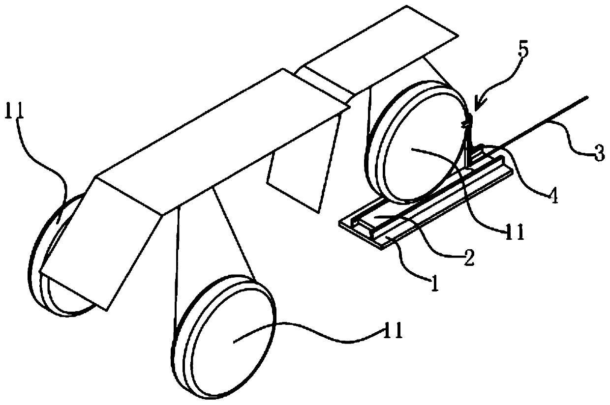
[0028] The protective device for hemodynamic monitoring includes a guide plate 1, a positioning plate 2, a traction member 3, a guiding mechanism and a positioning mechanism. Specifically, as figure 1 , Figure 4 and Figure 7 As shown, the guiding mechanism is arranged between the positioning pallet 2 and the guiding pallet 1, and is used for guiding the longitudinal movement of the positioning pallet 2 along the upper surface of the guiding pallet 1. The guide mechanism includes a guide rod 1a and a guide wheel 22. The guide rod 1a is located on both sides of the guide pallet 1, and a guide groove 1b opposite to it is opened on the guide rod 1a. The guide wheels 22 are respectively arranged on the four corners of the positioning pallet 2, the positioning pallet 2 can be inserted between the two guide rods 1a, and the four guide wheels 22 are respectively located in the guide groove 1b. The positioning pallet 2 is connected with a traction member 3, and the traction member...

Embodiment 2

[0032] Embodiment 2. This embodiment is improved on the basis of Embodiment 1. The content described in Embodiment 1 is also included in this embodiment, and will not be repeated here.

[0033] The technical solution in this embodiment is basically the same as the technical solution in Embodiment 1, the difference is that in this embodiment, the linkage component is a connecting rod and two rocker arms that are connected to the two clamping claws 5 one by one. , the connecting rod includes a main rod and two support rods, one end of the two support rods is fixedly connected with one end of the main rod, and the other ends of the two support rods are hinged with the two rocker arms in a one-to-one correspondence. The transmission assembly includes a dial and a driving motor, the dial is fixedly connected with the output shaft of the driving motor, and one end of the total rod is hinged at the edge of the dial. The output shaft of the driving motor drives the dial to rotate, and...

Embodiment 3

[0034] Embodiment 3. This embodiment is improved on the basis of Embodiment 2. The content described in Embodiment 1 is also possessed by this embodiment, and details will not be repeated here.

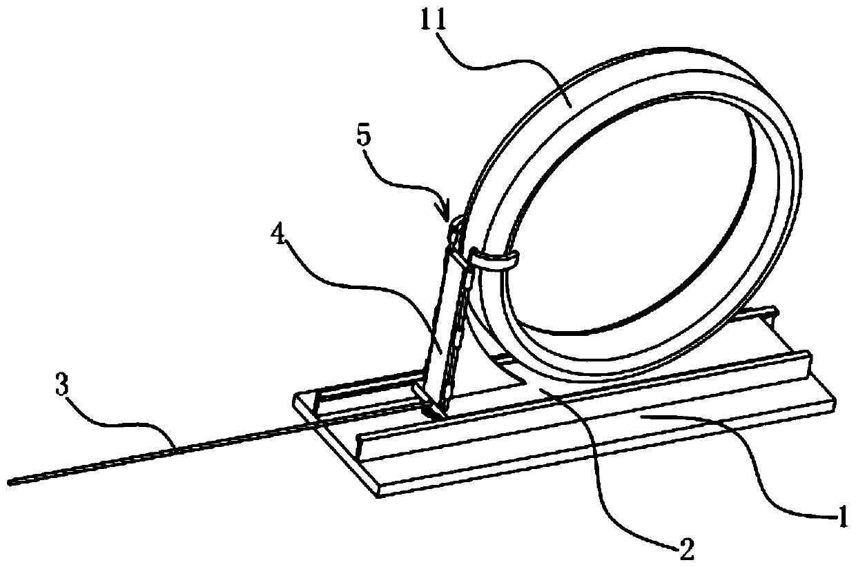
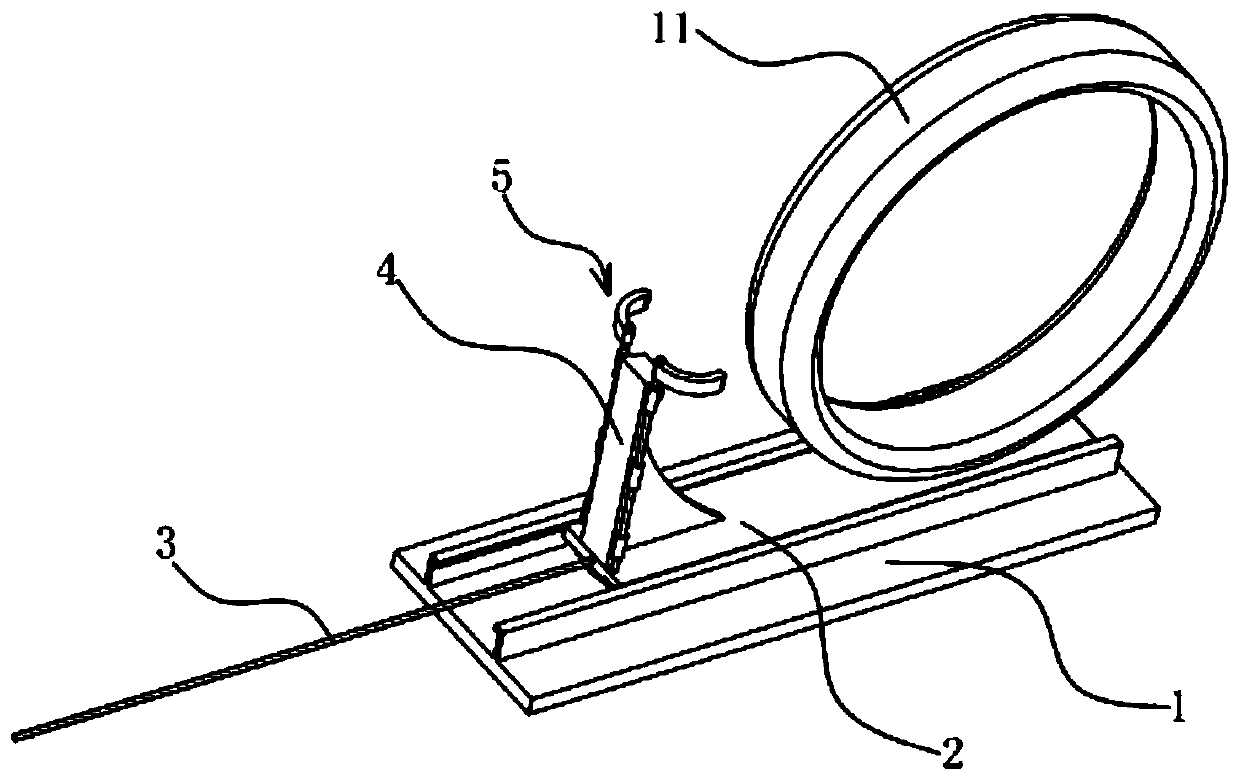
[0035] The technical solution in this embodiment is basically the same as the technical solution in Embodiment 2, the difference is that in this embodiment, the positioning mechanism includes a support that is fixed on the positioning pallet 2 and has an abutment for the object to be measured 11 to abut against. The abutting piece 4 on the surface; both sides of the abutting surface are provided with a clamping claw 5, and the clamping claw 5 is positioned on the abutting piece 4, and each clamping claw 5 is fixedly connected with a handle. The relative setting of the two clamping claws 5; the clamping claws 5 are driven to swing by the manipulation handle, and the claw mouth between the two clamping claws 5 is enlarged or locked, so that the two clamping claws 5 hold the object 11 to ...


PUM


Abstract

The invention provides a protection device for hemodynamic monitoring, and belongs to the technical field of hemodynamic monitoring. The protection device comprises a long-strip-shaped guide supporting plate and a positioning supporting plate; the positioning supporting plate and the guide supporting plate are connected through a guide mechanism capable of enabling the positioning supporting plateto longitudinally move along the upper surface of the guide supporting plate; the positioning supporting plate is connected with a traction piece; and the positioning supporting plate is provided with a positioning mechanism which can position a to-be-measured object on the positioning supporting plate and can release the to-be-measured object positioned on the positioning supporting plate. According to the protection device for hemodynamic monitoring, two clamping jaws are driven by a transmission assembly and a linkage assembly to position an object to be monitored and the positioning supporting plate, positioning is reliable, and a reliable protection function is achieved. According to the protection device for hemodynamic monitoring, clamping and loosening of a clamping piece are achieved through collision of a transmission piece and a fixing column, a stroke limiting convex body is embedded into the positioning groove to form self-locking of the clamping piece, and clamping operation is convenient.

Description

technical field [0001] The invention relates to the technical field of hemodynamic monitoring, in particular to a protection device for hemodynamic monitoring. Background technique [0002] The patient in the ICU is critically ill and has unstable hemodynamics, requiring radial artery and femoral artery catheterization to monitor blood pressure dynamically. Due to the change of the patient's body position or the operation room of the medical staff, the arterial indwelling catheter is different, discounted or prolapsed, and the arterial indwelling catheter needs to be re-inserted, which increases the pain of the patient and the chance of bloodstream infection, and also increases the economic burden of the patient. In order to avoid the occurrence of the above situation, designing a protective device for hemodynamic monitoring is a difficult problem to be solved urgently by those skilled in the art. [0003] Chinese patent CN201820414346.X relates to the field of medical tech...

Claims


Application Information

Patent Timeline
Patent Type & Authority Applications(China)
IPC IPC(8): A61B5/0215A61B5/00
CPCA61B5/0215A61B5/70
Inventor 吴莹欧尽南钟燕军
Owner THE SECOND XIANGYA HOSPITAL OF CENT SOUTH UNIV
Why Eureka
Try Eureka