
A kind of degreasing method of plate degreasing system for cold rolling mill

A technology of cold rolling mill and oil system, applied in metal rolling, metal rolling, manufacturing tools, etc., can solve the problems of lower yield rate, wrong layer of plate coiling, and failure to meet actual production requirements, etc., to improve yield rate Effect

Active Publication Date: 2021-12-14
佛山市业恒不锈钢有限公司
View PDF4 Cites 0 Cited by
  • Summary
  • Abstract
  • Description
  • Claims
  • Application Information

AI Technical Summary

Problems solved by technology

[0002] The existing plate cold rolling mill needs to spray high-viscosity rolling oil to the plate rolling area and add corresponding additives when needed. Therefore, after the plate passes through the cold rolling mill, a certain amount of rolling oil will remain on the surface of the plate. Oil production, when there is too much residual process rolling oil on the surface of the plate, it is easy to produce misalignment when the plate is coiled, and even fall out when the plate is rolled at high speed, causing accidents, and the surface of the plate after annealing will produce marks and oil spots, resulting in Quality defects greatly reduce the finished product, so an oil removal device needs to be installed at the exit of the cold rolling mill
[0003] For the problem of residual high-viscosity rolling oil, the existing cold-rolling mill generally adopts a reciprocating motion of a soft oil scraper to directly contact the surface of the plate, thereby wiping off the residual high-viscosity rolling oil on the surface of the plate, such as a copper strip cold finishing mill, Using rolling oil with relatively high kinematic viscosity, the speed can reach 800m / min during the test run, and the scraper-type degreasing method can meet the high-speed rolling requirements of rolling mills using high-viscosity rolling oil, but in actual production In the middle, the oil scraper is easy to entrain impurities such as copper shavings, scratch the surface of the plate, reduce the yield, and cannot meet the actual production requirements

Method used


Image

  • A kind of degreasing method of plate degreasing system for cold rolling mill

Examples


Embodiment Construction

[0019] The following will clearly and completely describe the technical solutions in the embodiments of the present invention with reference to the accompanying drawings in the embodiments of the present invention. Obviously, the described embodiments are only some, not all, embodiments of the present invention.

[0020] In describing the present invention, it should be understood that the terms "upper", "lower", "front", "rear", "left", "right", "top", "bottom", "inner", " The orientation or positional relationship indicated by "outside", etc. is based on the orientation or positional relationship shown in the drawings, and is only for the convenience of describing the present invention and simplifying the description, rather than indicating or implying that the referred device or element must have a specific orientation, so as to Specific orientation configurations and operations, therefore, are not to be construed as limitations on the invention.

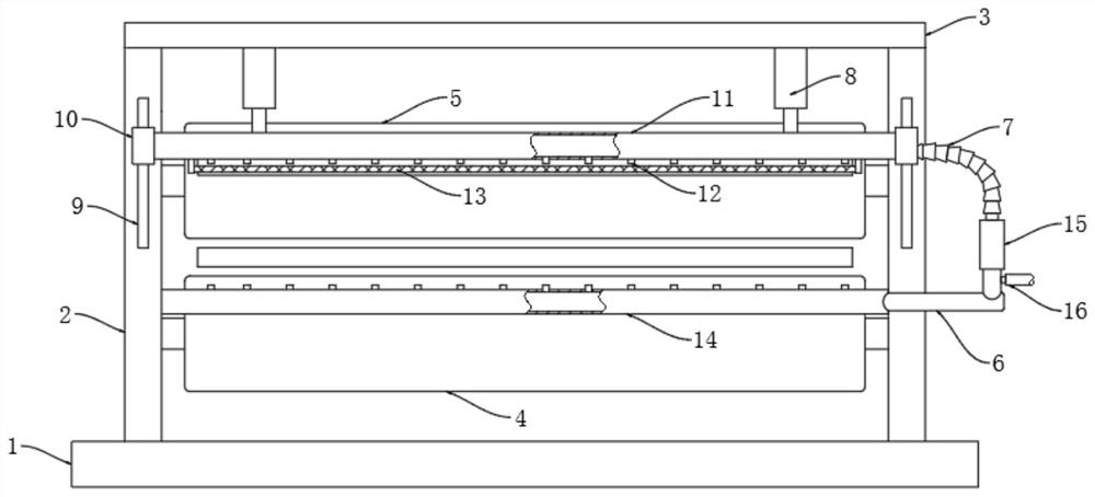
[0021] refer to figure 1...


PUM


Abstract

The invention discloses a degreasing method for a plate degreasing system for a cold rolling mill. It includes the following steps: S1, start the electric push rod, push the cold air pipe down, and the oil-absorbing sponge is attached to the surface of the plate; S2, high-pressure gas delivery, send the high-pressure gas into the vortex tube through the high-pressure air intake pipe, the hot gas enters the heat pipe, and the cold air enters the cold air. Tube; S3, temperature difference manufacturing, the temperature of the lower end of the oil-absorbing sponge rises, the temperature of the upper end of the oil-absorbing sponge drops, and the temperature difference between the upper and lower parts of the oil-absorbing sponge; S4, the oil-water absorption of the plate, the oil-water at the lower end of the oil-absorbing sponge continues to move to the upper end of the oil-absorbing sponge , so that the lower end of the oil-absorbing sponge can continuously absorb the oil stains on the surface of the board. The invention can efficiently remove the residual rolling liquid on the surface of the plate by setting the oil-absorbing sponge and the temperature difference manufacturing mechanism, and avoids the surface of the plate from being scratched by impurities such as iron filings and copper filings during friction, and improves the yield of the cold rolling mill. , which can better meet the actual production requirements.

Description

technical field [0001] The invention relates to the technical field of cold rolling mills, in particular to a degreasing method of a plate degreasing system for cold rolling mills. Background technique [0002] The existing plate cold rolling mill needs to spray high-viscosity rolling oil to the plate rolling area and add corresponding additives when needed. Therefore, after the plate passes through the cold rolling mill, a certain amount of rolling oil will remain on the surface of the plate. Oil production, when there is too much residual process rolling oil on the surface of the plate, it is easy to produce misalignment when the plate is coiled, and even fall out when the plate is rolled at high speed, causing accidents, and the surface of the plate after annealing will produce marks and oil spots, resulting in Quality defects will greatly reduce the finished product, so an oil removal device needs to be installed at the exit of the cold rolling mill. [0003] For the pr...

Claims


Application Information

Patent Timeline
Patent Type & Authority Patents(China)
IPC IPC(8): B21B45/02
CPCB21B45/0269
Inventor 柳友香
Owner 佛山市业恒不锈钢有限公司
Learn More