Aggregate precooling system
A technology of aggregate and pre-cooling, applied in the direction of cooler, refrigerator, pre-treatment control, etc., can solve the problem of poor pre-cooling effect of aggregate, and achieve the effect of increasing the quantity, shortening the construction period and reducing the production cost.
- Summary
- Abstract
- Description
- Claims
- Application Information
AI Technical Summary
Problems solved by technology
Method used
Image
Examples
Embodiment 1
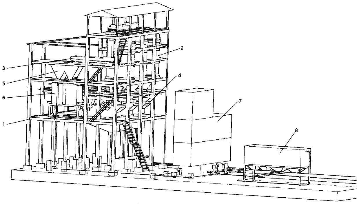
[0088] Such as Figure 1 to Figure 18 As shown, a kind of aggregate precooling system of the present embodiment comprises:
[0089] Cold material building 1;
[0090] The pre-cooling part 2 is fixed on the cold material building 1 and includes several aggregate pre-cooling warehouses 9;
[0091] The material conveying part 3 includes a sliding part slidably arranged on the cold material building 1. After the sliding part slides and communicates with one of the aggregate pre-cooling bins 9, the aggregate is transported into the aggregate pre-cooling bin 9;
[0092] There are several discharging parts 4, and the discharging parts 4 and the aggregate pre-cooling bins 9 are provided in one-to-one correspondence.
[0093] Aggregate needs to be pre-cooled before use to reduce the calorific value of the concrete mixture. Most of the existing aggregate precooling uses a belt conveyor as the carrier, and the aggregate is precooled during the aggregate transmission process; the preco...
Embodiment 2
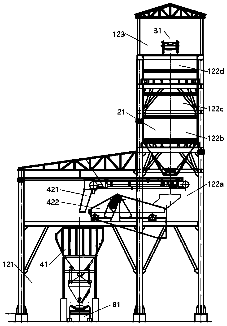
[0101] In this embodiment, on the basis of Embodiment 1, the structure and function of the precooling unit 2 will be described.
[0102] Such as Figure 1 to Figure 16 As shown, in the specific embodiment provided by the present disclosure, the aggregate pre-cooling bin 9 can be configured as any suitable structure. As an option, the aggregate pre-cooling bin 9 includes a bin body 91 and a pre-cooling assembly 92 located in the bin body 91;
[0103] The bin body 91 includes a pre-cooling bin 911;
[0104] Pre-cooling assembly 92 includes:
[0105] The partition 921 is located in the pre-cooling bin 911 and divides the pre-cooling bin 911 into a plurality of interconnected pre-cooling spaces. The partition 921 is opened and closed to allow the aggregate to pass from one pre-cooling space to another pre-cooling space;
[0106] The pre-cooling part 922 includes a spraying part located at one end of the pre-cooling bin 911 and a water collecting part at the other end of the pre...
Embodiment 3
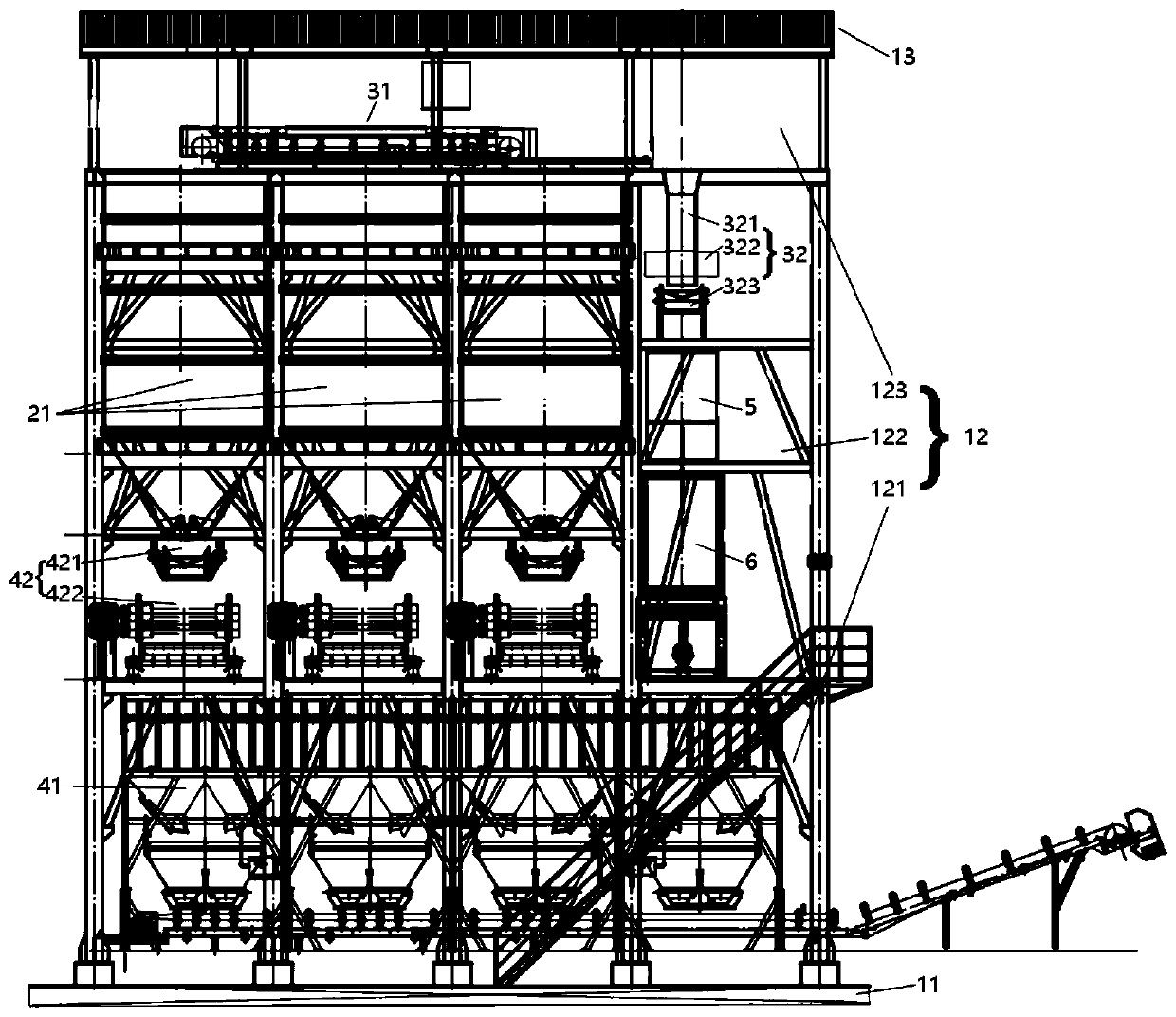
[0189] as attached Figure 1-4 as well as Figure 17-18 As shown, this embodiment is based on Embodiments 1 and 2, and describes other parts that make up the aggregate precooling system of this invention.
[0190] In the specific implementation manner provided in the present disclosure, the delivery part 3 can be configured as any suitable structure. As an option, the delivery section 3 includes:
[0191] The material distribution component 31 is slidably arranged on the cold material building 1 and transports the aggregate to the aggregate pre-cooling warehouse 9;
[0192] The sand sending component 32 separates the aggregate and the sand, and transports the sand to the sand storage bin 5 .
[0193] Now supplement the structure of the material conveying part 3, wherein, the material distribution component 31 undertakes the aggregate and distributes the aggregate. Since there are multiple aggregate pre-cooling warehouses 9, in order to achieve a simplified structure, reduce...
PUM
| Property | Measurement | Unit |
|---|---|---|
| diameter | aaaaa | aaaaa |
| particle diameter | aaaaa | aaaaa |
| particle diameter | aaaaa | aaaaa |
Abstract
Description
Claims
Application Information
 - R&D
- Intellectual Property
- Life Sciences
- Materials
- Tech Scout
- Unparalleled Data Quality
- Higher Quality Content
- 60% Fewer Hallucinations
Browse by: Latest US Patents, China's latest patents, Technical Efficacy Thesaurus, Application Domain, Technology Topic, Popular Technical Reports.
© 2025 PatSnap. All rights reserved.Legal|Privacy policy|Modern Slavery Act Transparency Statement|Sitemap|About US| Contact US: help@patsnap.com


