A double-roller leather processing system

A processing system and leather technology, applied in leather manufacturing, raw hide/leather/fur manufacturing equipment, small raw hide/large raw hide/leather/fur treatment, etc., can solve problems such as poor effect and low fat removal efficiency, and achieve shortening The effect of improving the processing cycle, improving the efficiency of degreasing, and reducing the accumulation of fat

Active Publication Date: 2021-10-22
浙江牧羊人实业股份有限公司
View PDF0 Cites 0 Cited by
  • Summary
  • Abstract
  • Description
  • Claims
  • Application Information

AI Technical Summary

Problems solved by technology

[0006] The purpose of the present invention is to provide a double-roller leather processing system with high fat removal efficiency and good effect to solve the problem of low fat removal efficiency and poor effect of existing leather processing devices

Method used


Image

  • A double-roller leather processing system
  • A double-roller leather processing system
  • A double-roller leather processing system

Examples


Embodiment 1

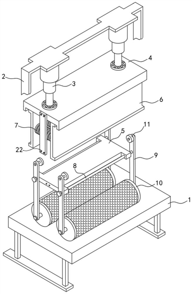
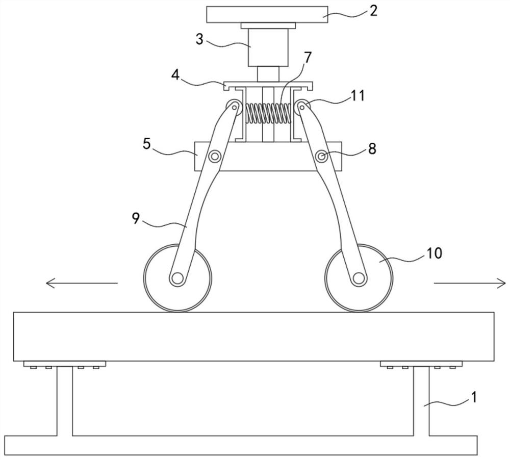
[0024] Such as Figure 1-2 As shown, a double-roller leather processing system includes a base 1, the upper end of the base 1 is fixedly connected with a fixed frame 2, the lower end of the fixed frame 2 is fixedly connected with a limiting plate 4 through a plurality of hydraulic cylinders 3, and the lower end of the limiting plate 4 passes through The connecting bar 22 is fixedly connected with a fixed plate 5, and two sliding plates 6 are slidably connected between the limiting plate 4 and the fixed plate 5. The limiting plate 4, the fixed plate 5 and the base 1 are arranged in parallel, and the two ends of the limiting plate 4 Bend downwards to form ribs for limiting the sliding plate 6 .

[0025] An elastic member 7 is fixedly connected between the two sliding plates 6, and both sides of the fixed plate 5 are rotatably connected with a rotating shaft 8, and both ends of the rotating shaft 8 are fixedly connected with a rotating rod 9, and the middle and upper parts of the...

Embodiment 2

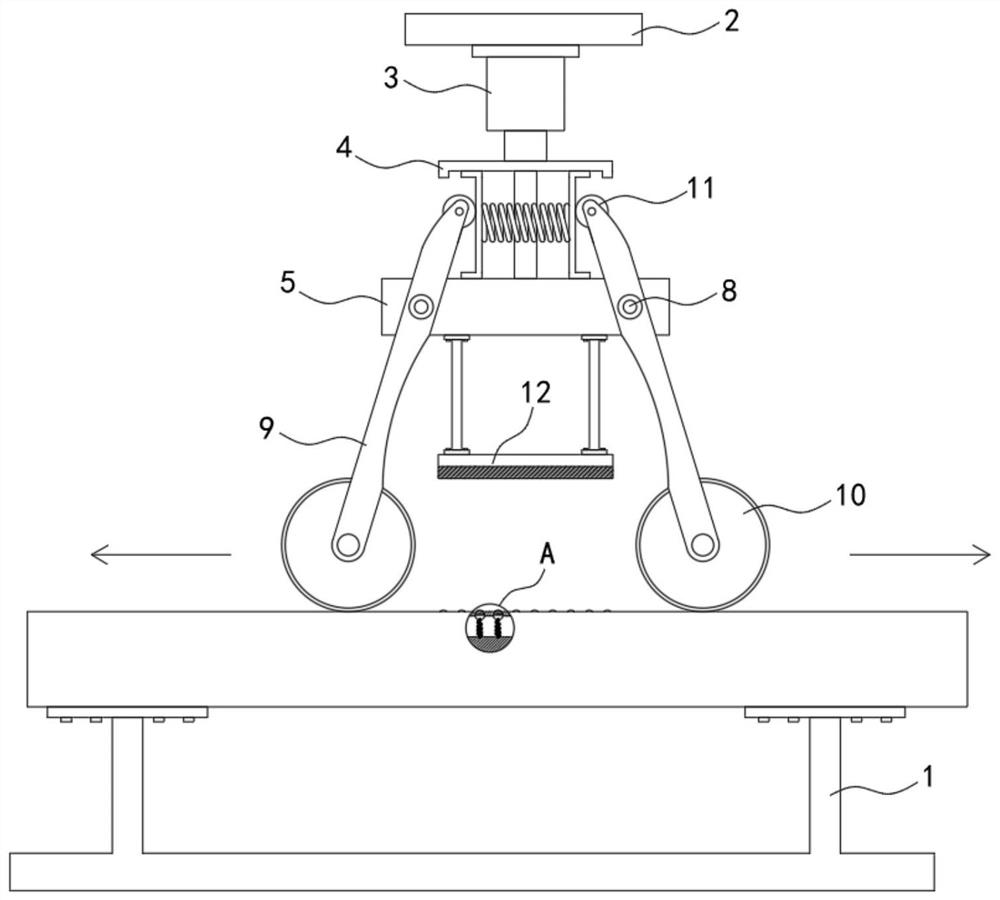
[0028] Such as Figure 3-4 As shown, the difference between this embodiment and Embodiment 1 is that the elastic member 7 is a plurality of return springs, and the plurality of return springs are parallel and fixedly connected between two sliding plates 6 .

[0029] The lower end of the fixed plate 5 is fixedly connected with a permanent magnet plate 12, the base 1 is provided with a cavity 13, and the upper end array of the cavity 13 has a plurality of striking holes 14, and the striking holes 14 are provided with magnetic striking balls 15, and the striking balls 15 Repel with the same polarity between the permanent magnet plates 12, and the batting ball 15 is fixedly connected with the bottom of the cavity 13 through the vibrating spring 16.

[0030] When this embodiment is in use, along with the continuous downward movement of the limiting plate 4, under the action of the magnetic field of the permanent magnet plate 12, the hitting ball 15 will be moved downward, the vibra...

Embodiment 3

[0032] Such as Figure 5 As shown, the difference between this embodiment and Embodiment 1 is that the elastic member 7 is an elastic airbag 17, and the inside of the elastic airbag 17 is sealed, and the elastic airbag 17 can be made of solvent-resistant rubber, and the elastic airbag 17 is fixed on two pieces. Between the sliding plates 6 , the elastic airbag 17 expands and contracts along the sliding direction of the sliding plates 6 .

[0033] The elastic airbag 17 is connected with a one-way liquid inlet pipe 18 and a one-way liquid discharge pipe 19. Specifically, the middle part of the elastic airbag 17 is fixedly connected with a fixed ring, and the fixed ring divides the elastic airbag 17 into two, and the one-way liquid inlet Both the pipe 18 and the one-way liquid discharge pipe 19 are fixedly connected to the fixed ring. When the elastic airbag 17 is stretched or compressed, the position of the fixed ring remains unchanged. The one-way liquid inlet pipe 18 is used t...


PUM


Abstract

The invention belongs to the field of leather processing, and in particular relates to a double-roller leather processing system, which includes a base. The connecting bar is fixedly connected with a fixed plate, and two sliding plates are slidably connected between the limiting plate and the fixed plate, and an elastic member is fixedly connected between the two sliding plates, and both sides of the fixed plate are rotatably connected with a rotating shaft, and the two sides of the rotating shaft Both ends are fixedly connected with a rotating rod, and a pressure roller is connected to rotate between the two rotating rods connected to the upper end of the same rotating shaft. The present invention is provided with two pressure rollers, and when in use, the two pressure rollers are respectively squeezed toward both sides, on the one hand, the accumulation of fat can be reduced, and the resistance of the pressure rollers in the rolling process can be reduced; on the other hand, it can double Greatly improve the degreasing efficiency and shorten the processing cycle.

Description

technical field [0001] The invention belongs to the field of leather processing, in particular to a double-roller leather processing system. Background technique [0002] Leather is denatured and non-perishable animal skin obtained through physical and chemical processing such as depilation and tanning. In people's daily life utensils. [0003] In the process of leather production and manufacturing, in order to facilitate the operation of various processes in the later stage and prevent oil spots on the finished leather, it is generally necessary to remove the fat in the subcutaneous tissue layer, epidermis layer and dermis layer in the raw hide. [0004] The degreasing of raw hides and skins is generally divided into mechanical methods and chemical methods. Among them, mechanical methods generally destroy free fat and fat glands by rolling. At present, most of them are carried out by pressing rollers. However, because the fat in raw hides is relatively Many, during the ex...

Claims


Application Information

Patent Timeline
Patent Type & Authority Patents(China)
IPC IPC(8): C14B1/02C14B17/00C14C1/08
CPCC14B1/02C14B17/00C14C1/08
Inventor 杨群英陈莹
Owner 浙江牧羊人实业股份有限公司
Why Eureka
Try Eureka