Eureka AIR delivers breakthrough ideas for toughest innovation challenges, trusted by R&D personnel around the world.

Soil sampling and detecting device

A detection device and soil sampling technology, which is applied in the direction of sampling devices, measuring devices, soil material testing, etc., can solve the problems of low sampling efficiency, easy to slip, time-consuming and labor-intensive handling process, etc., to save time and effort in the operation process and increase the application Effects of increased range, sampling efficiency

Inactive Publication Date: 2020-08-14
苏波
View PDF1 Cites 25 Cited by
  • Summary
  • Abstract
  • Description
  • Claims
  • Application Information

AI Technical Summary

Problems solved by technology

Although the sampling device improves the accuracy of soil sample pollutant determination, manual sampling is required, which is time-consuming and laborious, and the sampling efficiency is low
[0004] Traditional soil sampling and testing devices need to be transported to the soil surface in the process of testing soil for on-site sampling and immediate on-site testing to prevent the sampling from being brought back to the laboratory. Longer storage time will affect the detection accuracy. Before the sampling process, the soil sampling and detection device is transferred to the soil surface. Because the soil surface is relatively loose, the traditional roller contact is used to push the transfer, and the contact friction with the conveying ground is low, and the push transfer process is prone to slipping. It affects the normal movement of domestic vehicles, and the bending depends on the manual handling process. The handling process is time-consuming and laborious, which affects the overall efficiency of detection

Method used


Image

  • Soil sampling and detecting device
  • Soil sampling and detecting device
  • Soil sampling and detecting device

Examples


Embodiment Construction

[0025] The technical solution of the present invention will be further described in detail below in conjunction with the accompanying drawings, but the protection scope of the present invention is not limited to the following description.

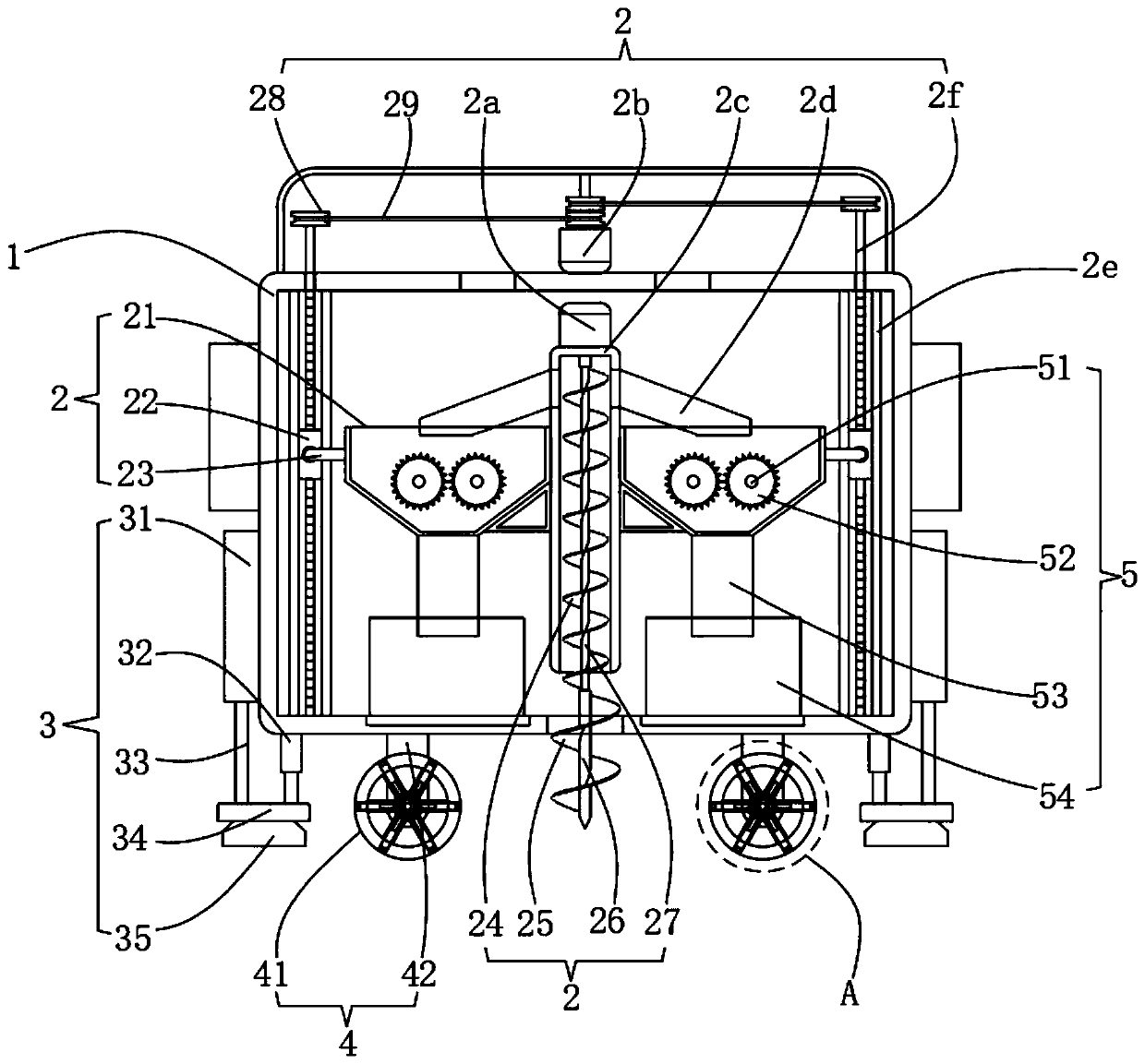
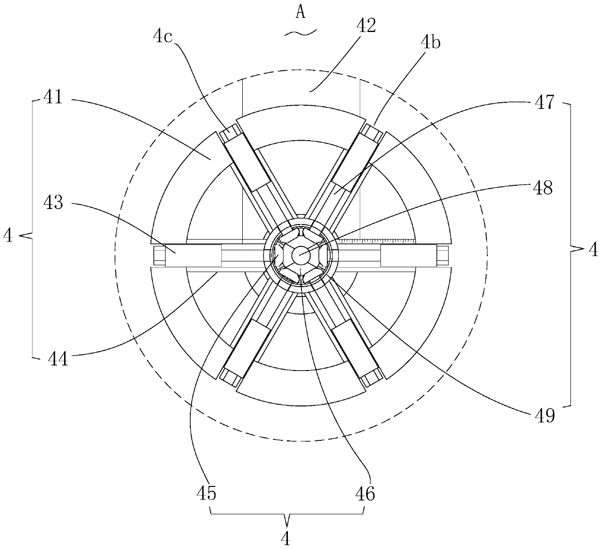
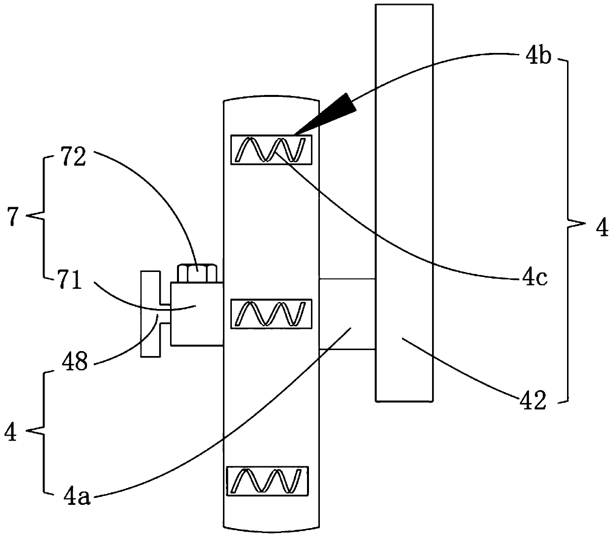
[0026] The present invention provides a soil sampling and detection device, please refer to Figure 1 to Figure 7 As shown, among them, figure 1 A schematic diagram of a partial explosion structure of the soil sampling and detection device provided by the present invention; figure 2 for figure 1 The schematic diagram of the partially enlarged structure shown at A; image 3 for figure 1 Schematic diagram of the enlarged structure of the mobile adjustment mechanism shown in the side view direction; Figure 4 for figure 1 A schematic diagram of the local structure of the side view direction of the box shown; Figure 5 for figure 1 A schematic diagram of the local structure of the box shown in the top view direction; Figure 6 for fig...


PUM


Abstract

The invention provides a soil sampling and detecting device. The soil sampling and detecting device comprises a box body, a soil sampling mechanism, a supporting adjusting mechanism, a movable adjusting mechanism, a crushing and detecting mechanism, an auxiliary operating mechanism and a limiting mechanism. The movable adjusting mechanism suitable for adjusting and transferring different road surfaces is connected with the bottom of the box body and comprises a hub, a supporting plate, a rectangular inner threaded pipe, a rectangular sleeve, a first bevel gear, a second bevel gear, an outer threaded rod, a T-shaped rotating rod, a circular box, a third rotating shaft and a bent plate. According to the soil sampling and detecting device provided by the invention, the form of the corresponding hub needs to be adjusted in the transferring process for pushing and transferring; the device can be suitable for rolling of different types of road surfaces; and when the road condition of the soil conveying road surface is poor, transferring can be conducted in a manual carrying mode; time and labor are saved in the operation process; the working efficiency is improved; the device is suitablefor transferring of two kinds of road surfaces; and the application range of the transferring process is widened.

Description

technical field [0001] The invention relates to the technical field of farmland soil sampling and detection devices, in particular to a soil sampling and detection device. Background technique [0002] With the development of industry and the wide application of pesticides and fertilizers, the pollution of soil is becoming more and more common. From the perspective of environmental protection, the detection, evaluation and improvement of soil are becoming more and more important. Determination of representative values ​​of environmental quality factors to determine environmental quality or pollution levels and their changing trends. What we usually refer to as soil monitoring refers to soil environmental monitoring, which generally includes technical content such as point sampling, sample preparation, analysis methods, result characterization, data statistics, and quality evaluation. The detection and treatment of soil first needs to detect the quality of the soil to determ...

Claims


Application Information

Patent Timeline
Patent Type & Authority Applications(China)
IPC IPC(8): G01N1/08G01N1/28G01N33/24
CPCG01N1/08G01N1/286G01N33/24
Inventor 苏波
Owner 苏波
Why Eureka
Eureka Blog
Learn More