Composite Fireproof Cable

A technology for fire-resistant cables and cable core wires, applied in the direction of insulated cables, cables, circuits, etc., can solve the problems of cable burning, reduce fire spread, economic losses, etc., achieve the strengthening of the outer protective layer of cables, reasonable structural design, and protection of cable cores line effect

Active Publication Date: 2021-10-26
人民电缆集团有限公司
View PDF8 Cites 0 Cited by
  • Summary
  • Abstract
  • Description
  • Claims
  • Application Information

AI Technical Summary

Problems solved by technology

[0002] Cables are laid in many occasions, including exposed cables, power laid in the air and buried cables, but no matter where the cables are laid, there is a risk of fire. When a group cable fire is caused by an external fire, the cable must have very good fire resistance. When there is a flame outside or one of the cables spontaneously ignites, the flame will burn the outer protective layer of the cable, and then quickly ignite the surrounding cables, causing the cable to burn. Aggregated combustion causes the fire to spread rapidly, causing serious economic losses. When there is a flame, the distance between the outer protective layers of the cable is relatively close, so the flame can be transmitted quickly. If the outer protective layer of the burning cable can be separated automatically , away from other cables, it is bound to reduce the speed of flame propagation and reduce the spread of fire
[0003] In addition, in order to increase the shear resistance of the cable, a large number of metal filaments are arranged in the outer protective layer of the cable, which can increase the strength of the outer protective layer of the cable, but these metal wires often only have the ability to increase the strength of the outer protective layer of the cable. When there is a flame, the metal wire cannot protect the cable core, and there are problems in use

Method used


Image

  • Composite Fireproof Cable
  • Composite Fireproof Cable
  • Composite Fireproof Cable

Examples


Embodiment Construction

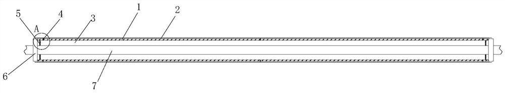
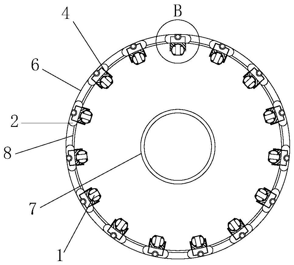
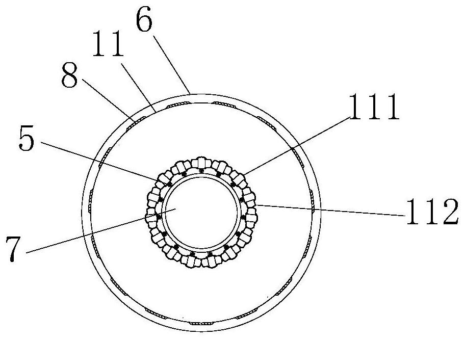
[0021] Such as figure 1 and figure 2 As shown, the composite fireproof cable includes more than one positioning ring 6 equidistantly arranged, and a through hole 3 is opened in the middle of the positioning ring 6, and the cable core wire 7 passes through the through hole on each positioning ring 6, and two adjacent positioning rings 6 An outer protective layer 8 is wrapped between the rings 6, and more than one opening 11 is provided around the outer protective layer 8 on the outer protective layer 8, and assembly steps are arranged on the positioning ring 6 facing the outer protective layer 8. surface 61, the two sides of the outer protective layer 8 are set on the assembly step surface 61, each opening 11 is sealed by a sealing strip 2, and a steel wire device 1 is arranged at the bottom of each sealing strip 2, and the steel wire device 1 They are all fixedly connected to the outer wall surface of the cable core wire 7 through the first spring 5, the first spring 5 is st...


PUM


Abstract

The invention discloses a composite fireproof cable, which comprises more than one positioning rings arranged equidistantly. A through hole is opened in the middle of the positioning rings, and the cable core wire passes through the through holes on each positioning ring. An outer protective layer is set on each package, and more than one opening is opened around the outer protective layer on the outer protective layer. The positioning ring is provided with an assembly step surface facing the outer protective layer. On the step surface, each opening is sealed by a sealing strip, and a steel wire device is arranged at the bottom of each sealing strip; the cable of the present invention can be used as a reinforced protection for the outer protective layer of the cable by utilizing the steel wire structure. Increase the strength of the outer protective layer of the cable, and at the same time use the steel wire structure to achieve the purpose of secondary wrapping the cable core wire. It not only has a good fireproof line, but also has a very good shear resistance, and the structural design is more reasonable.

Description

technical field [0001] The invention relates to the field of cables, in particular to a composite fireproof cable. Background technique [0002] Cables are laid in many occasions, including exposed cables, power laid in the air and buried cables, but no matter where the cables are laid, there is a risk of fire. When a group cable fire is caused by an external fire, the cable must have very good fire resistance. When there is a flame outside or one of the cables spontaneously ignites, the flame will burn the outer protective layer of the cable, and then quickly ignite the surrounding cables, causing the cable to burn. Aggregated combustion causes the fire to spread rapidly, causing serious economic losses. When there is a flame, the distance between the outer protective layers of the cable is relatively close, so the flame can be transmitted quickly. If the outer protective layer of the burning cable can be separated automatically , away from other cables, it is bound to red...

Claims


Application Information

Patent Timeline
Patent Type & Authority Patents(China)
IPC IPC(8): H01B7/17H01B7/22H01B7/282H01B7/29
CPCH01B7/17H01B7/225H01B7/282H01B7/29
Inventor 肖汉杰王亚迪陈亚芝
Owner 人民电缆集团有限公司
Why Eureka
Try Eureka