Pole piece structure and lithium ion battery

A lithium-ion battery and pole piece technology, which is applied to battery electrodes, secondary batteries, structural parts, etc., can solve the problems of poor battery self-discharge consistency, poor self-discharge consistency, etc., to avoid internal short circuit and reduce physical self-discharge Effect

Pending Publication Date: 2020-08-14
JIANGSU ZENIO NEW ENERGY BATTERY TECH CO LTD
View PDF0 Cites 8 Cited by
  • Summary
  • Abstract
  • Description
  • Claims
  • Application Information

AI Technical Summary

Problems solved by technology

The more burrs, the greater the physical self-discharge, which causes the consistency of battery self-discharge to become poor.
[0005] In view of this, it is necessary to provide a pole piece structure and a lithium-ion battery to solve the problem of poor self-discharge consistency

Method used


Image

  • Pole piece structure and lithium ion battery
  • Pole piece structure and lithium ion battery
  • Pole piece structure and lithium ion battery

Examples


Embodiment 1

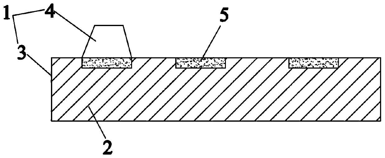
[0039] Such as figure 1 As shown, a pole piece structure includes a current collector 1 and an active material layer 2. The current collector 1 has a main body area 3 and a tab area 4 extending from the main body area. The active material layer 2 is arranged on the surface of the main body area 3. A resistive layer 5 is provided on the tab side of the body region 3 . The resistance value of the resistance layer 5 is greater than or equal to 10 -2 Ω. The resistance layer 5 is an insulating adhesive layer, and the insulating adhesive layer is pasted intermittently on the surface of the active material layer 2 on the ear side of the main body area 3 .

[0040] The preparation method of the pole piece structure is specifically as follows:

[0041] 1) Coating the active material slurry on the surface of the current collector 1 in the main body area 3, forming the active material layer 2 after rolling and drying;

[0042] 2) Die-cut tabs in the blank current collector area adjacen...

Embodiment 2

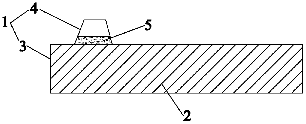
[0045] Such as figure 2 As shown, the difference between this embodiment and embodiment 1 is that: the surface of the current collector 1 at the root of the tab region 4 is provided with a resistive layer 5 . The resistance layer 5 is a paint layer, and the paint layer contains at least one of conductive material, semiconductor material, insulating material and PTC material.

[0046] The preparation method of the pole piece structure is specifically as follows:

[0047] 1) Coating the active material slurry on the surface of the current collector 1 in the main body area 3, forming the active material layer 2 after rolling and drying;

[0048] 2) Coating the resistance layer slurry on the blank current collector area adjacent to the main body area 3, and forming the resistance layer 5 after rolling and drying;

[0049] 3) Die-cut tabs in the area adjacent to the main body area 3 to obtain the tab area 4. The root of the tab area 4 has a resistance layer 5, and the head of th...

Embodiment 3

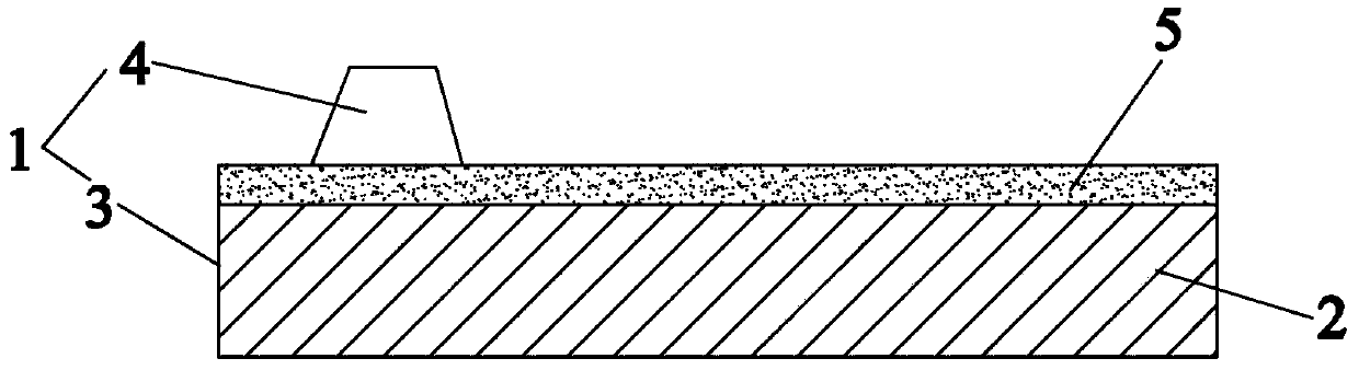
[0052] Such as image 3 As shown, the difference between this embodiment and embodiment 1 is that: the resistance layer 5 is continuously provided on the tab side of the main body region 3 . The resistance layer 5 is an active material layer that has undergone deactivation treatment, that is, acid treatment, laser treatment or high temperature treatment is performed on the active material layer 2 located on the ear side of the main body region 3 .

[0053] The preparation method of the pole piece structure is specifically as follows:

[0054] 1) Coating the active material slurry on the surface of the current collector 1 in the main body area 3, forming the active material layer 2 after rolling and drying;

[0055] 2) Deactivate the area of ​​the active material layer 2 adjacent to the blank current collector to obtain the resistance layer 5;

[0056] 3) Die-cut tabs in the blank current collector area adjacent to the resistance layer 2 to form the tab area 4, and obtain the...


PUM

PropertyMeasurementUnit
electrical resistanceaaaaaaaaaa
widthaaaaaaaaaa
thicknessaaaaaaaaaa

Abstract

The invention belongs to the technical field of lithium ion batteries, and especially relates to a pole piece structure. The pole piece structure comprises a current collector and an active substancelayer, the current collector is provided with a main body region and a tab region extending from the main body region, the active substance layer is arranged on the surface of the main body region, and a resistance layer is arranged on the tab side of the main body region and / or the root of the tab region. In addition, the invention also relates to a lithium ion battery, the lithium ion battery comprises a positive plate, a negative plate, diaphragms arranged between the positive plate and the negative plate at intervals, and an electrolyte, and the positive plate and / or the negative plate adopt / adopts the pole piece structure. Compared with the prior art, burrs on the die cutting edge of the current collector can be prevented from piercing a diaphragm to form an internal short circuit, physical self-discharge is reduced, and the consistency of self-discharge is improved.

Description

technical field [0001] The invention belongs to the technical field of lithium ion batteries, and in particular relates to a pole piece structure and a lithium ion battery. Background technique [0002] Lithium-ion batteries have been widely used in notebook computers, mobile communications, etc. due to their advantages such as high specific energy and high voltage. In addition, in the field of electric vehicles, mobile base stations, and energy storage power stations, there is a larger demand market. In this application, lithium-ion batteries are no longer used in single-cell applications, but more in series, parallel or series-parallel. used in the form of a battery pack. [0003] When a battery in the battery pack has a problem, it will affect the entire battery module, and the difference in battery self-discharge is the focus of attention. A battery with inconsistent self-discharge will have a large difference in SOC after a period of storage, which will greatly affect...

Claims


Application Information

Patent Timeline
Patent Type & Authority Applications(China)
IPC IPC(8): H01M4/66H01M4/70H01M10/0525
CPCH01M4/667H01M4/70H01M10/0525Y02E60/10
Inventor 王汭邹武元於洪将姜斌龙绘锦
Owner JIANGSU ZENIO NEW ENERGY BATTERY TECH CO LTD
Why Eureka
Try Eureka