A conveying wood splitter for biomass power generation

A biomass power generation and wood splitting machine technology, which is applied in the direction of wood splitting devices, manufacturing tools, wood processing appliances, etc., can solve the problems of high-power electrical equipment that cannot be used, the circuit is not perfected, and the labor intensity of operators is increased. Achieve the effects of preventing impact, preventing blade shaking, and reducing labor intensity

Active Publication Date: 2022-04-19
瑞安市驰恒传动设备有限公司
View PDF8 Cites 0 Cited by
  • Summary
  • Abstract
  • Description
  • Claims
  • Application Information

AI Technical Summary

Problems solved by technology

[0002] Biomass power generation is the power generation using the biomass energy of biomass. It is a kind of renewable energy power generation, including direct combustion power generation of agricultural and forestry waste, gasification power generation of agricultural and forestry waste, waste incineration power generation, landfill gas power generation , Biogas power generation, the circuits in some rural areas of our country have not been perfected, and some high-power electrical equipment cannot be used, such as firewood equipment. The old circuits cannot support the operation of high-power firewood equipment, and then need to use biomass power reach normal power consumption
[0003] The wood splitting equipment mainly presses the firewood to the blade of the knife head to split in half through mechanical transmission. At present, every time a piece of wood is split, a new piece of firewood needs to be added manually, which leads to a great labor intensity for the operator. increase, and the existing cutter is directly fixed inside the wood splitter, so when the blade of the cutter is damaged and curled, it cannot be replaced, which may affect the cutting efficiency of the wood splitter

Method used


Image

  • A conveying wood splitter for biomass power generation
  • A conveying wood splitter for biomass power generation
  • A conveying wood splitter for biomass power generation

Examples


Embodiment

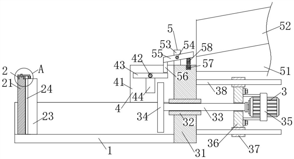
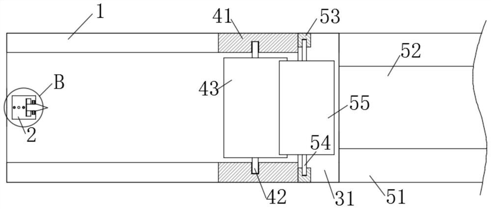
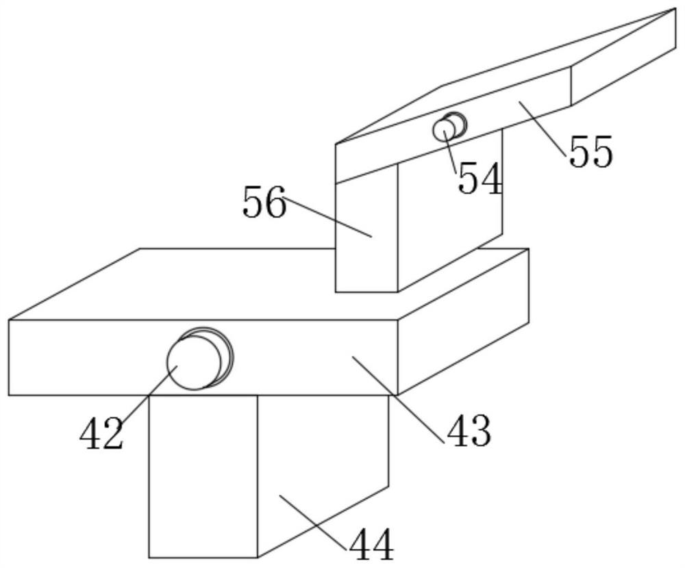
[0027] Example: such as Figure 1-6 As shown, a wood splitting machine for biomass power generation in the present invention includes a semi-cylinder 1, a splitting mechanism 2 is installed on the inner wall of one end of the semi-cylinder 1, and a pushing mechanism 3 is installed on the end of the semi-cylinder 1 away from the splitting mechanism 2. The top of the half cylinder 1 is equipped with a linkage mechanism 4 away from the end of the splitting mechanism 2, and the upper end of the pushing mechanism 3 is equipped with a blanking mechanism 5.

[0028] Split mechanism 2 comprises knife seat 21, and knife seat 21 is fixedly connected on the end inner wall of semi-cylinder 1, and knife seat 21 is provided with T-shaped chute 22 near the side of pushing mechanism 3, and the top of T-shaped chute 22 and knife The outside of the seat 21 is connected, and the inside of the T-shaped chute 22 is slidably connected with a cutter 23. The cutter 23 is fixedly connected to both sid...


PUM


Abstract

The invention discloses a wood splitting machine for biomass power generation, which comprises a half cylinder, a splitting mechanism is installed on the inner wall of one end of the half cylinder, and a pushing mechanism is installed at the end of the half cylinder away from the splitting mechanism. The threaded rod rotates, and the threaded rod pushes the push plate to move through the threaded cylinder. When the push plate pushes the wood to complete the cutting, it moves back. The pushed back pushes the swing block, and the swing block drives the plate to rotate. One end of the plate rises and pushes the push block to the top Then push the inclined plate through the push block, so that the other end of the inclined plate turns over, and then the inclined plate blocked at the opening of the semi-circular chute moves down, and then the wood falls from the semi-circular chute into the inside of the semi-cylinder by gravity, just By placing multiple pieces of wood continuously inside the semicircular chute at one time, the wood can be automatically placed inside the semicircle, which greatly reduces the labor intensity of the operator.

Description

technical field [0001] The invention relates to a firewood splitter, in particular to a conveying firewood splitter for biomass power generation, and belongs to the technical field of firewood chopping equipment. Background technique [0002] Biomass power generation is the power generation using the biomass energy of biomass. It is a kind of renewable energy power generation, including direct combustion power generation of agricultural and forestry waste, gasification power generation of agricultural and forestry waste, waste incineration power generation, landfill gas power generation , Biogas power generation, the circuits in some rural areas of our country have not been perfected, and some high-power electrical equipment cannot be used, such as firewood equipment. The old circuits cannot support the operation of high-power firewood equipment, and then need to use biomass power reach normal power consumption [0003] The wood splitting equipment mainly presses the firewo...

Claims


Application Information

Patent Timeline
Patent Type & Authority Patents(China)
IPC IPC(8): B27L7/06
CPCB27L7/06
Inventor 汪江池林瑞汉
Owner 瑞安市驰恒传动设备有限公司
Why Eureka
Try Eureka