
A method for arranging ultraviolet lamps in secondary water supply ultraviolet disinfection equipment

A technology for ultraviolet disinfection and secondary water supply, applied in water/sewage treatment equipment, chemical instruments and methods, water treatment sites, etc., can solve the problem of damage to lamp tubes and quartz sleeves, incorrect calculation methods, and reduced floor space and other issues to achieve the effect of eliminating the influence of uncertain factors, ensuring scientificity and accuracy, and being easy to produce and install

Active Publication Date: 2020-11-20
重庆昕晟环保科技有限公司
View PDF1 Cites 0 Cited by
  • Summary
  • Abstract
  • Description
  • Claims
  • Application Information

AI Technical Summary

Problems solved by technology

3) Medium-voltage high-intensity ultraviolet lamp: emit multi-wavelength electromagnetic waves (200-600nm), only about 27% to 44% of the ultraviolet energy is within the range of UVC, only 7% of the output is near 254nm, and the photoelectric conversion rate is 10% to 15%, which is one-third of the low-pressure lamp, and its energy consumption is 3-3.5 times that of the low-pressure lamp; the operating temperature is 600-800°C, the pressure is 0.013MPa-1.33MPa, and the energy in the lamp is not turned on. Mercury is in a liquid state, so it needs to be stored and used very carefully, otherwise there is a risk of leakage; in addition, due to the high operating temperature of the medium-pressure lamp tube, it is easy to cause fouling of the lamp tube, which will greatly reduce the effective ultraviolet intensity of the lamp tube, and easily cause damage to the lamp. The tube and quartz sleeve are damaged, and a specially designed descaling device is required for normal operation. It is not suitable for use in places such as secondary water supply tanks where there are no professional guards; Up to 1500W, so the number of lamps used can be greatly reduced, and the occupied area is also reduced accordingly. It is suitable for large sewage treatment plants, rainstorm overflow and occasions with high space utilization requirements
But in view of the following two reasons, this calculation method is incorrect: 1) when tap water flows through the disinfection container of the ultraviolet disinfection equipment, it flows from one end to the other at one time, and there is no back and forth flow; The attenuation of the water flow is attenuated according to the exponential level as the distance increases, so the ultraviolet radiation received by the water flow is mainly affected by the nearest ultraviolet lamp, and other ultraviolet lamps have little effect

Method used


Image

  • A method for arranging ultraviolet lamps in secondary water supply ultraviolet disinfection equipment
  • A method for arranging ultraviolet lamps in secondary water supply ultraviolet disinfection equipment
  • A method for arranging ultraviolet lamps in secondary water supply ultraviolet disinfection equipment

Examples


Embodiment 1

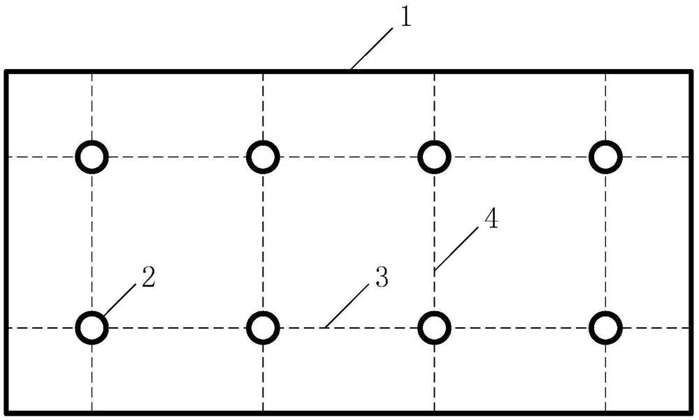
[0046] The invention discloses a method for arranging ultraviolet lamps in secondary water supply ultraviolet disinfection equipment, which comprises the following steps:

[0047] Step 1. Detect the ultraviolet intensity at different distances from the center point of the ultraviolet lamp tube in tap water. When testing, first set up multiple detection points according to the different distances from the center point of the ultraviolet lamp tube, and then detect the corresponding value of each detection point. The ultraviolet intensity, the distance between the detection point and the center point of the ultraviolet lamp tube will be used as the farthest vertical distance between the tap water in the disinfection container and the center point of the ultraviolet lamp tube in the later design.

[0048] Step 2. According to the result of step 1, calculate the irradiation time required for the tap water to receive the effective dose of safe ultraviolet light at different distances...

Embodiment 2

[0073] This embodiment is further described on the basis of embodiment 1 in conjunction with specific actual data, specifically as follows:

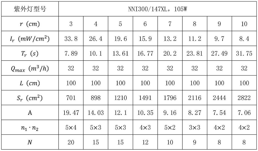
[0074] Step 1: Detect the ultraviolet intensity at different distances from the center point of the ultraviolet lamp tube in the tap water.

[0075] In this step, the ultraviolet lamp is a low-voltage, high-intensity ultraviolet lamp with a UVC output power of 105W and a model number of NNI300 / 147XL produced by Heraeus Special Lighting Co., Ltd., and the quartz tube is a product produced by Foshan Kewei Optoelectronics Co., Ltd.

[0076] The center point of the lamp tube refers to the midpoint of the axis of the UV lamp tube. The detection point is selected on the normal line of the lamp tube. The normal line of the lamp tube refers to the straight line passing through the center point of the lamp tube and perpendicular to the axis of the lamp tube; After the quartz sleeve is finished, put it in a special water tank and start running. Af...


PUM


Abstract

The invention discloses a method for arranging ultraviolet lamps in ultraviolet disinfection equipment for secondary water supply. The irradiation time required to receive the effective dose of safe ultraviolet rays at different distances from the center of the tube; 3. Calculate the theoretical minimum value of the cross-sectional area of ​​the corresponding disinfection container; 4. Determine the arrangement and number of ultraviolet lamps in the disinfection container; 5. First Determine the best arrangement scheme, and then determine the cross-sectional size of the disinfection container. The present invention determines the optimal arrangement scheme of ultraviolet lamps in the disinfection container under the requirement of meeting the maximum water flow rate through the method of quantitative calculation, and determines the cross-sectional size of the disinfection container so as to minimize the ineffectiveness of ultraviolet disinfection equipment. The risk of exerting the disinfection and sterilization effect provides an effective guarantee for the safety of drinking water.

Description

technical field [0001] The invention relates to the field of secondary water supply disinfection of urban water supply pipe network systems, in particular to a method for arranging ultraviolet lamps in secondary water supply ultraviolet disinfection equipment. Background technique [0002] As early as 1878, humans discovered that ultraviolet rays in sunlight have a sterilizing effect. The principle of ultraviolet sterilization is that ultraviolet rays of appropriate wavelengths can destroy the molecular structure of DNA or RNA in microbial cells, causing growth and regenerative cells to die, and achieve the effect of sterilization. Ultraviolet rays are divided into four different bands according to the wavelength range: UVA (400-315nm), UVB (315-280nm), UVC (280-200nm) and vacuum ultraviolet (200-100nm). Since UVA and UVB are outside the range of microbial absorption peaks, the sterilizing speed is very slow, so in practical applications, this part of ultraviolet light is a...

Claims


Application Information

Patent Timeline
Patent Type & Authority Patents(China)
IPC IPC(8): C02F1/32
CPCC02F1/325C02F2201/3225C02F2201/3227C02F2303/04C02F2307/14
Inventor 高晓昆程立刘新贵
Owner 重庆昕晟环保科技有限公司
Learn More