
Pneumatic optical sight error image processing method and system

A line-of-sight error and image processing technology, which is applied in the field of aerospace experiments, can solve the problems of not being able to obtain key information for line-of-sight error evaluation, unable to extract original image information, and statistical analysis, etc.

Pending Publication Date: 2020-08-18
CHINA ACAD OF AEROSPACE AERODYNAMICS
View PDF4 Cites 2 Cited by
  • Summary
  • Abstract
  • Description
  • Claims
  • Application Information

AI Technical Summary

Problems solved by technology

At the same time, there is currently a lack of effective methods for line-of-sight error image processing, and information extraction and statistical analysis of the original test images cannot be performed, and key information for line-of-sight error evaluation cannot be obtained.

Method used


Image

  • Pneumatic optical sight error image processing method and system
  • Pneumatic optical sight error image processing method and system
  • Pneumatic optical sight error image processing method and system

Examples


Embodiment Construction

[0064] Exemplary embodiments of the present disclosure will be described in more detail below with reference to the accompanying drawings. Although exemplary embodiments of the present disclosure are shown in the drawings, it should be understood that the present disclosure may be embodied in various forms and should not be limited by the embodiments set forth herein. Rather, these embodiments are provided for more thorough understanding of the present disclosure and to fully convey the scope of the present disclosure to those skilled in the art. It should be noted that, in the case of no conflict, the embodiments of the present invention and the features in the embodiments can be combined with each other. The present invention will be described in detail below with reference to the accompanying drawings and examples.

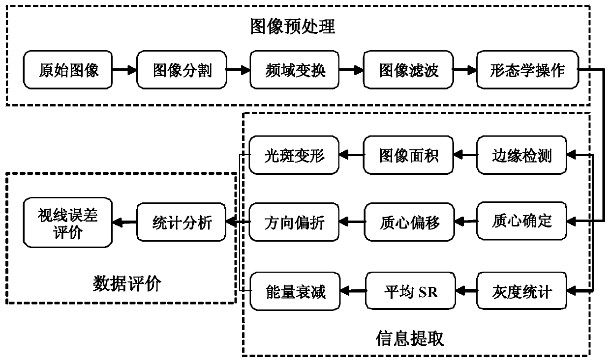
[0065] figure 1 It is a flow chart of the image processing method for aero-optical line-of-sight error provided by the present invention. Such as figure 1 ...


PUM


Abstract

The invention discloses a pneumatic optical sight error image processing method and system. Image preprocessing is completed through the steps of image segmentation, frequency domain transformation, image filtering, morphological operation and the like on a light beam image passing through a test flow field, and then the area ratio, the sight line error and the average Sterner ratio of a light beam are calculated through edge detection, centroid determination and gray scale statistics methods. According to the pneumatic optical sight error image processing method and system, information extraction and statistical analysis are carried out on an original test image to obtain key information of sight line error evaluation.

Description

technical field [0001] The invention belongs to the technical field of aerospace experiments, and in particular relates to an aero-optical line-of-sight error image processing method and system. Background technique [0002] With the development of our country's national defense, the flight speed of various missiles is getting higher and higher, and the requirements for its guidance accuracy are also getting higher and higher. However, when a high-speed missile flies in the atmosphere, a severe aerodynamic heating and high-temperature environment will be generated around the missile, and the guidance system of the missile is generally equipped with optical glass on the head to facilitate receiving the image of the target. At the same time, jets are used for cooling, resulting in a mixed laminar flow field between the cooling airflow and the external airflow. After the target light passes through the aerodynamic thermal field and the mixed laminar flow field, serious aero-op...

Claims


Application Information

Patent Timeline
IPC IPC(8): G06T7/00G06T7/13G06T7/155G06T7/66G06T5/00G06T5/30
CPCG06T7/0004G06T7/13G06T7/155G06T7/66G06T5/30G06T5/70Y02T90/00
Inventor 石伟龙吴宇阳甘才俊
Owner CHINA ACAD OF AEROSPACE AERODYNAMICS
Learn More