Eureka AIR delivers breakthrough ideas for toughest innovation challenges, trusted by R&D personnel around the world.

Transformer thermal fault monitoring device and method based on transformer substation inspection robot

A technology for inspection robots and monitoring devices, applied in transformer testing, measuring devices, radiation pyrometry, etc., can solve problems such as reducing equipment failure detection rate, heavy workload, and poor human-machine collaboration ability, and achieve rapid identification. And the effect of diagnosis, improvement of maintenance level, and high fault detection rate

Inactive Publication Date: 2020-08-18
苏州求臻智能科技有限公司
View PDF0 Cites 5 Cited by
  • Summary
  • Abstract
  • Description
  • Claims
  • Application Information

AI Technical Summary

Problems solved by technology

[0002] Substation equipment has been in operation for a long time. In order to ensure the safe and stable operation of electrical equipment and timely discover equipment defects or hidden dangers, operators need to conduct inspections on site equipment. The workload is heavy and the efficiency is low, and the inspection results often fail to achieve the expected results.
At present, it is more common to use hand-held thermal imagers to conduct manual inspections of electrical equipment on a regular basis. This method makes the workload of monitoring personnel heavy. In addition, unplanned temperature measurement tasks such as power protection before festivals and peak holidays cause monitoring People are prone to fatigue, which increases the unsafety of work, and also reduces the detection rate of equipment failure
In addition, due to the rapid development of the power system in recent years, there are more power equipment, and some substations are far away, so the temperature measurement is often not carried out during the peak load period, so that some thermal defects cannot be discovered in time, which also reduces the risk of equipment failure. The detection rate
[0003] Existing substation inspection robots can realize automatic inspection of substations to a certain extent and liberate labor force, but there are defects such as low integration level, incomplete inspection function, and poor human-machine cooperation ability, which cannot meet the requirements of intelligent integration of electrical equipment inspection requirements

Method used


Image

  • Transformer thermal fault monitoring device and method based on transformer substation inspection robot
  • Transformer thermal fault monitoring device and method based on transformer substation inspection robot
  • Transformer thermal fault monitoring device and method based on transformer substation inspection robot

Examples


Embodiment Construction

[0029] The following will clearly and completely describe the technical solutions in the embodiments of the present invention in conjunction with the accompanying drawings in the specific embodiments of the present invention. Apparently, the described embodiments are only some of the embodiments of the present invention, not all of them. Based on the embodiments of the present invention, all other embodiments obtained by persons of ordinary skill in the art without making creative efforts belong to the protection scope of the present invention.

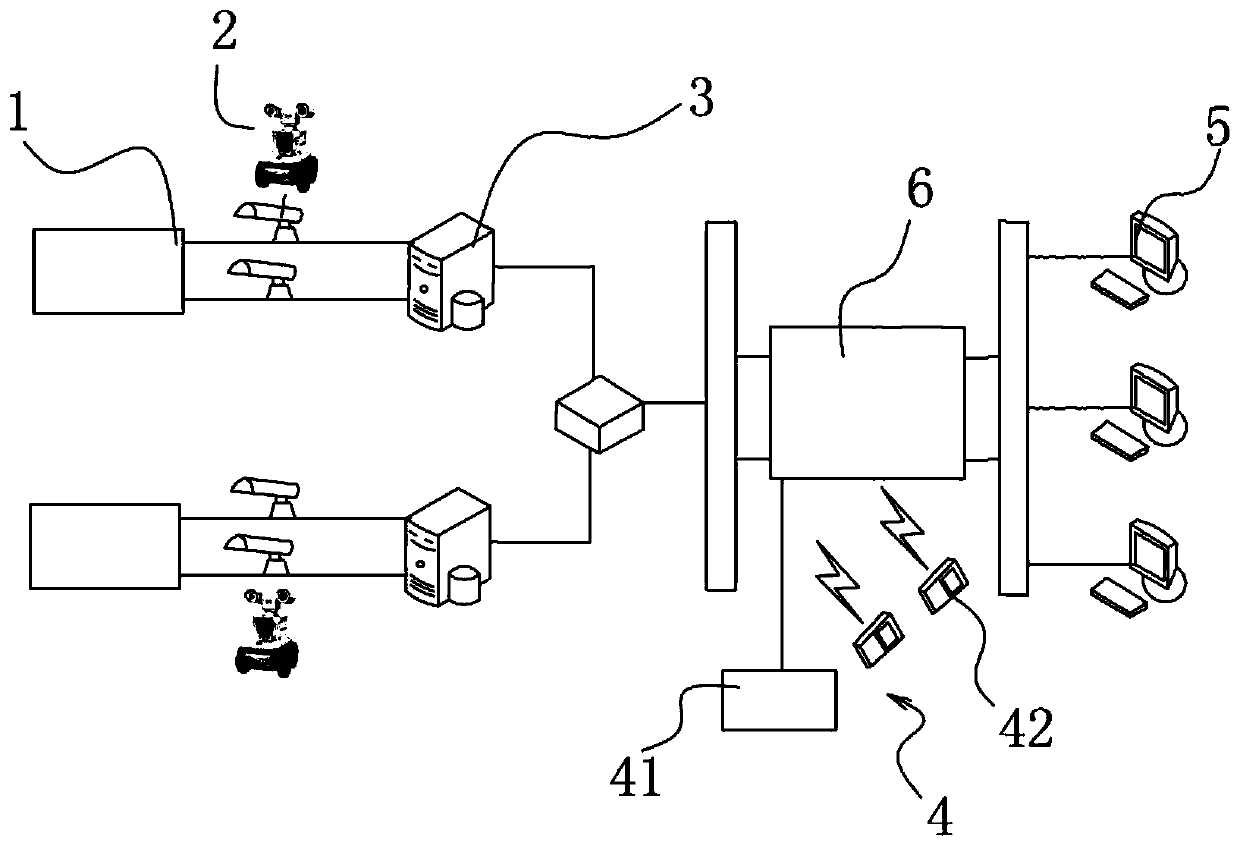
[0030] see Figure 1-4 This specific embodiment provides a technical solution: the transformer overheat fault monitoring device based on the substation inspection robot platform includes at least one infrared thermal imaging camera 2 that is arranged in the fault-prone area of ​​the transformer 1 and can collect thermal imaging images of the transformer , the infrared thermal imaging camera 2 is connected with the on-site industrial c...


PUM


Abstract

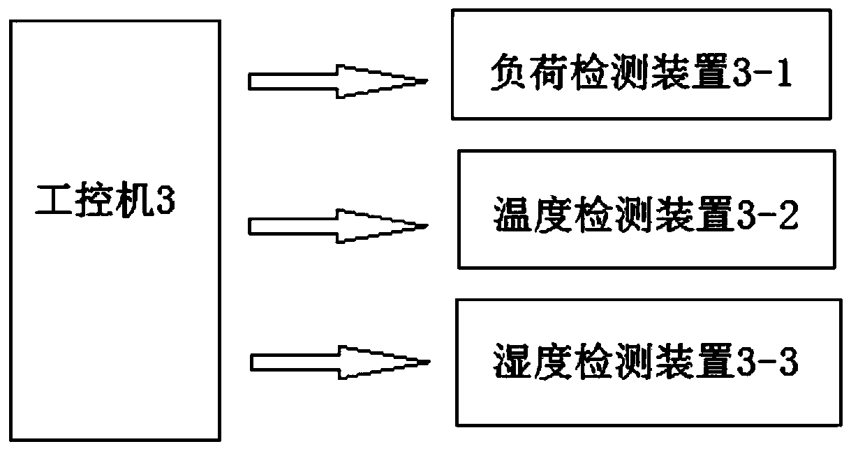
The invention discloses a transformer thermal fault monitoring device and method based on a transformer substation inspection robot. An infrared thermal imaging camera is connected with an industrialpersonal computer in a wireless communication mode, the industrial personal computer is connected with an alarm mechanism and a monitoring terminal, and the industrial personal computer is also connected with a server for storing a transformer thermal image. The alarm mechanism comprises any one or more of a sound-light alarm device or a mobile short message receiving terminal; the industrial personal computer is further connected with a load detection device used for detecting the load of the transformer, a temperature detection device used for detecting the environment temperature and a humidity detection device used for detecting the environment humidity. The infrared imaging device is integrated on a transformer substation inspection robot platform, collected transformer substation infrared image information is identified in a non-contact monitoring mode, rapid identification and diagnosis of the parts, the degrees and the types of potential faults in the early stage of a transformer are achieved, and the beneficial effects of being safe, reliable and efficient are achieved.

Description

technical field [0001] The invention relates to the technical field of transformer thermal fault monitoring, in particular to a transformer thermal fault monitoring device and method based on a substation inspection robot. Background technique [0002] Substation equipment has been in operation for a long time. In order to ensure the safe and stable operation of electrical equipment and timely discover equipment defects or hidden dangers, operators need to inspect the on-site equipment. The workload is heavy and the efficiency is low, and the inspection results often fail to achieve the expected results. At present, it is more common to use hand-held thermal imagers to conduct manual inspections of electrical equipment on a regular basis. This method makes the workload of monitoring personnel heavy. In addition, unplanned temperature measurement tasks such as power protection before festivals and peak holidays cause monitoring People are prone to fatigue, which increases the...

Claims


Application Information

Patent Timeline
Patent Type & Authority Applications(China)
IPC IPC(8): G06T7/00G06T7/90G08B21/18G08B25/10G06K9/00G01R31/62G01J5/00
CPCG06T7/0004G06T7/90G01R31/62G01J5/00G08B25/10G08B21/18G06T2207/30108G01J2005/0077G06V20/52
Inventor 杨强胡颖泽
Owner 苏州求臻智能科技有限公司
Why Eureka
Eureka Blog
Learn More