A Synchronous Polarization Method for Partitioned Piezoelectric Elements

A piezoelectric element and electrode technology, which is applied in the field of synchronous polarization of partitioned piezoelectric elements, can solve the problems of inability to control polarization voltage intensity and polarization direction independently, difficulty in realizing polarization of piezoelectric elements, and inconsistent polarization intensity of partitions. , to avoid electrode surface damage, avoid breakdown, and use a wide range of effects

Active Publication Date: 2021-09-24
DALIAN UNIV OF TECH
View PDF11 Cites 0 Cited by
  • Summary
  • Abstract
  • Description
  • Claims
  • Application Information

AI Technical Summary

Problems solved by technology

At present, the polarization of piezoelectric materials usually uses a translation stage with a conductive probe to clamp and polarize the piezoelectric element, or covers the polarization with a planar electrode. These methods can only polarize a single segment of the piezoelectric element. However, for multiple Partitioned piezoelectric elements cannot be polarized synchronously at one time, and need to be polarized repeatedly
Repeated polarization will lead to thermal depolarization of the piezoelectric element, resulting in inconsistency in the polarization intensity of the partitions, and it is difficult to realize the polarization of the piezoelectric element in a hundred-micron-scale micro-section, let alone control the polarization voltage intensity and polarization of each partition independently. Direction, high cost and low efficiency of polarization equipment

Method used


Image

  • A Synchronous Polarization Method for Partitioned Piezoelectric Elements
  • A Synchronous Polarization Method for Partitioned Piezoelectric Elements
  • A Synchronous Polarization Method for Partitioned Piezoelectric Elements

Examples


Embodiment Construction

[0041] The present invention will be further described below in conjunction with technical solutions and accompanying drawings.

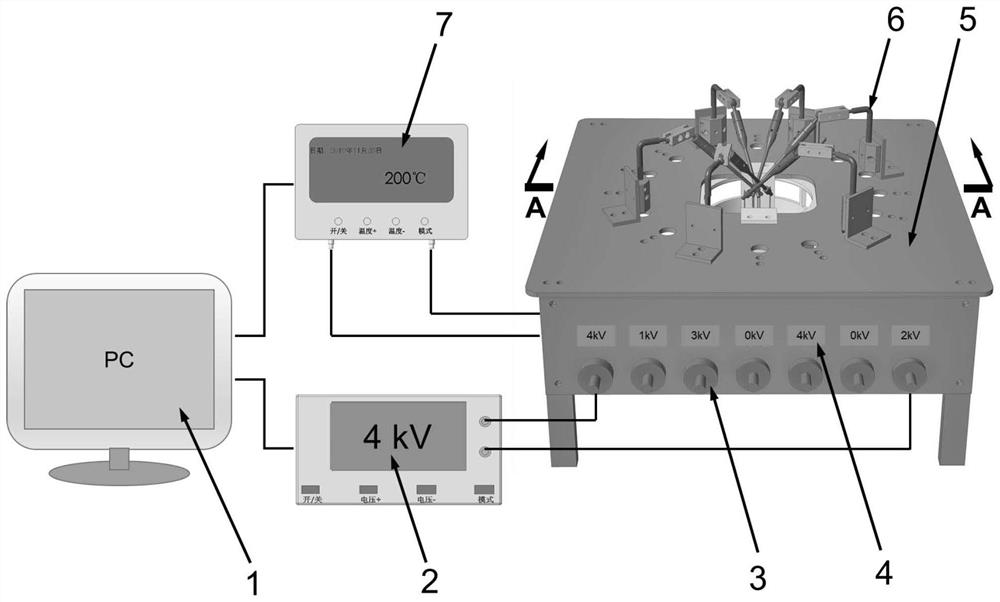
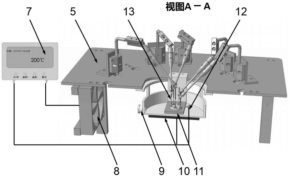
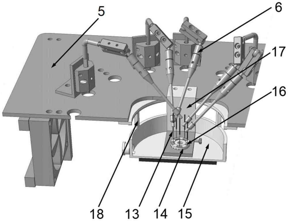
[0042] Such as Figure 1-Figure 4 As shown, the PC host computer 1 is connected to the high voltage generator 2 and the temperature control unit 7 to control the total output voltage of the high voltage generator 2 and the time variation curve of the polarization temperature. The high-voltage generator 2 is connected in parallel with the fixed end 19 of the voltage controller 3; the lower electrode connection plate 11 is connected with the sliding end 20 of one of the voltage controllers 3, and a high voltage is set to it; several elastic telescopic probes 13 are connected with the rest The sliding end 20 of the voltage controller 3 is connected, and by adjusting the resistance of the voltage controller 3, the voltage output of the elastic telescopic probe 13 with different sizes is realized, and the output voltage acts on the required polarization ...


PUM


Abstract

The invention discloses a method for synchronous polarization of partitioned piezoelectric elements, which belongs to the technical field of polarization of materials with piezoelectric characteristics. In the present invention, several elastic stretchable probes are used to touch the partitioned polarized electrodes on the piezoelectric element, and each polarized partition can obtain polarization voltages of different sizes and directions by controlling the relative voltage difference. synchronized polarization. The invention improves the polarization efficiency and avoids the problems of thermal depolarization of the piezoelectric element and inconsistency of the divisional polarization intensity caused by repeated polarization. The invention realizes the polarization of the tiny area of ​​hundreds of microns, the contact between the elastic stretchable probe and the tiny electrode is more sufficient, the polarization process is more stable, the electrode surface damage caused by uneven force is avoided, and the traditional polarization method is solved Difficulty in operation and positioning when polarizing tiny multi-section piezoelectric elements. At the same time, the PC host computer is used to control the high-voltage generator and the temperature control unit, which simplifies the polarization process and improves the polarization quality.

Description

technical field [0001] The invention belongs to the technical field of polarization of materials with piezoelectric characteristics, in particular to a method for synchronous polarization of partitioned piezoelectric elements. Background technique [0002] Piezoelectric elements have a special piezoelectric effect, which can realize the mutual conversion between mechanical vibration and electrical signals, and are widely produced into various high-performance piezoelectric devices. These devices have the characteristics of sensing, execution and control, and are widely used in medical Diagnosis, structural control, aerospace, weaponry and other fields have broad application prospects. [0003] Polarization is an important link to obtain piezoelectric properties of piezoelectric elements, and is the basis for realizing various functional characteristics of piezoelectric devices. Normally, polarization is a process in which a polarizing electric field is applied above the Cur...

Claims


Application Information

Patent Timeline
Patent Type & Authority Patents(China)
IPC IPC(8): H01L41/257
CPCH10N30/045
Inventor 王大志赵奎鹏袁钰恒王柱宗浩然梁军生
Owner DALIAN UNIV OF TECH
Why Eureka
Try Eureka