Direct-current microgrid system and control method

A technology of DC microgrid and control method, applied in the field of microgrid, can solve the problems of loss and low energy utilization rate, and achieve the effect of alleviating the pressure of peak regulation

Active Publication Date: 2020-08-18
GREE ELECTRIC APPLIANCES INC
View PDF8 Cites 6 Cited by
  • Summary
  • Abstract
  • Description
  • Claims
  • Application Information

AI Technical Summary

Problems solved by technology

The patent with the publication number CN110474371A discloses an online energy regulation method for a wind-solar-hydrogen integrated energy system, but this method uses excess electric energy to produce hydrogen, t

Method used


Image

  • Direct-current microgrid system and control method
  • Direct-current microgrid system and control method
  • Direct-current microgrid system and control method

Examples


Embodiment 1

[0044] Embodiment 1, a DC microgrid system.

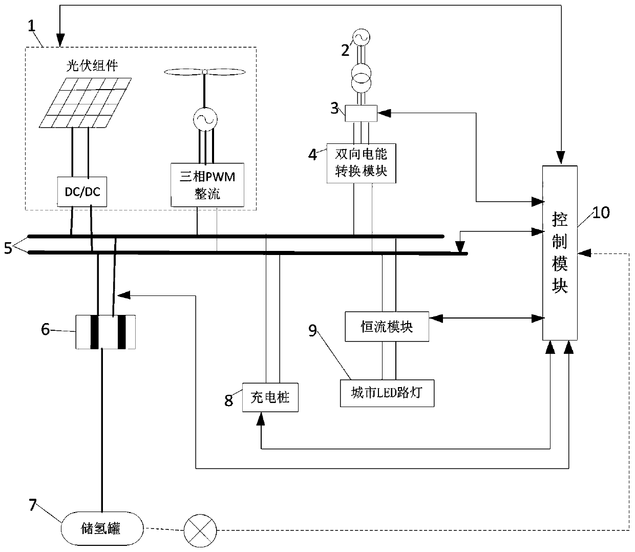
[0045] as attached figure 1 As shown, a DC microgrid system of this embodiment, the DC microgrid system is connected to the grid 2 through a switch after passing through the bidirectional power conversion module 4, and the DC microgrid system includes:

[0046] Renewable power generation module: generate power through renewable energy;

[0047]DC bus 5: the DC bus 5 connects the renewable power generation system 1 and the bidirectional power conversion module 4 to provide DC power for the DC microgrid system. The DC bus 5 is divided into positive and negative DC buses 5, which are The connection point of the generating system and the load;

[0048] Hydrogen storage module: the hydrogen storage module is connected to the DC bus 5 for generating and storing hydrogen;

[0049] Power consumption module: connected to the DC bus 5, using the DC power provided by the DC bus 5;

[0050] A control module 10, the control module 10 is res...

Embodiment 2

[0057] Embodiment 2, a control method of a DC microgrid system.

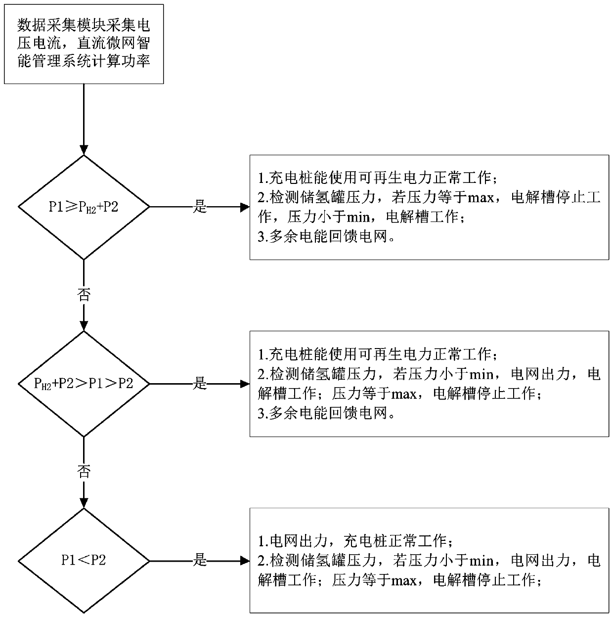
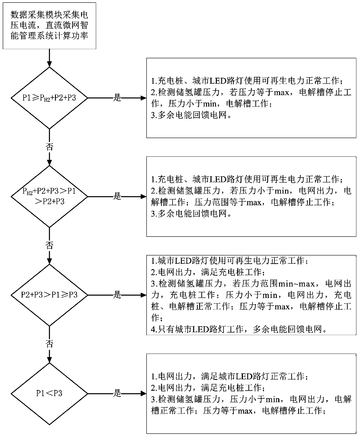
[0058] as attached figure 2 And attached image 3 As shown, this embodiment provides a control method for a DC microgrid system, which is applied to the control method for a DC microgrid system described in Embodiment 1, and the control method for a DC microgrid system includes a first control mode or a second control mode The second control mode corresponds to daytime work and nighttime work respectively. In this embodiment, the rated power of the electrolytic cell PH2 > the rated power of the charging pile 8 > P2 > the rated power of the urban LED street lamp 9 P3;

[0059] Among them, the first control mode such as figure 2 As shown, the specific steps are as follows:

[0060] The data collection module of the control module 10 collects various system information, and calculates the generated power and load power.

[0061] When P1≥PH2+P2, the electric energy of the renewable power generation system 1 sa...


PUM


Abstract

The invention provides a direct-current microgrid system and a control method. According to the invention, the DC microgrid system is connected with a power grid orderly via a bidirectional electric energy conversion module and a switch, and comprises a renewable power generation module, a direct-current bus, a hydrogen storage module, a power consumption module and a control module. In the direct-current microgrid system, power is distributed through the direct-current microgrid system, the hydrogen is produced, and the requirements for hydrogenation, charging (including hydrogen fuel cell vehicle charging and pure electric vehicle charging) and illumination are met; the wind power and photoelectricity are effectively consumed, the electric energy does not need to be converted multiple times in the alternating current and direct current forms, the energy utilization efficiency is improved, and the energy loss of the direct current microgrid is reduced. Moreover, the electric energy isfed back to the power grid, and the peak regulation pressure of the power grid is relieved.

Description

technical field [0001] The invention relates to the technical field of micro-grids, in particular to a DC micro-grid system and a control method. Background technique [0002] my country's hydrogen fuel cell vehicles and new energy lithium battery vehicles are developing rapidly, but both face the problem of hydrogen refueling and charging. Fuel cell vehicles include a hydrogen fuel cell system and a lithium battery system, which require both hydrogen refueling and charging. On the one hand, the current number of hydrogen refueling stations in my country is seriously insufficient, and the problems of hydrogen storage and transportation limit the development of hydrogen fuel cell vehicles. On the other hand, the charging power of DC charging piles accounts for an increasing proportion of the total load power of the distribution layer, which increases the difficulty of peak regulation of the power grid, and the planning and construction of the distribution network is facing s...

Claims


Application Information

Patent Timeline
IPC IPC(8): H02J1/10H02J1/14H02J3/38H02J3/28
CPCH02J1/10H02J1/14H02J3/28H02J3/381H02J2300/24H02J2300/28H02J2310/48Y02E10/56Y02E10/76Y02E60/36Y02E70/30
Inventor 覃世球肖彪刘智亮
Owner GREE ELECTRIC APPLIANCES INC
Why Eureka
Try Eureka