Energy supply system of on-line monitoring device on high-voltage transmission tower

A high-voltage transmission tower and monitoring device technology, which is applied in circuit devices, battery circuit devices, transportation and packaging, etc., can solve the problems of short life, low power, unstable energy supply, etc., and achieve long service life and stable energy supply Effect

Pending Publication Date: 2020-08-18
STATE GRID TIANJIN ELECTRIC POWER +1
View PDF0 Cites 2 Cited by
  • Summary
  • Abstract
  • Description
  • Claims
  • Application Information

AI Technical Summary

Problems solved by technology

[0002] At present, the sensors on the main body of the transmission line and the iron tower are currently powered by solar panels, micro-wind generators, batteries, etc., all of which are faced with problems such as unstable energy supply and short service life.
Some scholars proposed to use electrostatic induction to arrange the plates on the iron tower, relying on the capacitance between the line body and the plates to obtain energy, but faced with the problem of too small power and too large plate area
Some scholars have proposed to use the induction current technology to directly obtain stable electric energy from the transmission line body, but still face the difficulty of obtaining energy and transferring it to a low potential (on the iron tower)

Method used


Image

  • Energy supply system of on-line monitoring device on high-voltage transmission tower
  • Energy supply system of on-line monitoring device on high-voltage transmission tower
  • Energy supply system of on-line monitoring device on high-voltage transmission tower

Examples


Embodiment Construction

[0019] The present invention will be further described in detail below through the specific examples, the following examples are only descriptive, not restrictive, and cannot limit the protection scope of the present invention with this.

[0020] An energy supply system for an on-line monitoring device on a high-voltage transmission tower includes a wire CT energy acquisition unit, a laser energy transmission unit, and an energy storage and voltage stabilization unit connected in sequence.

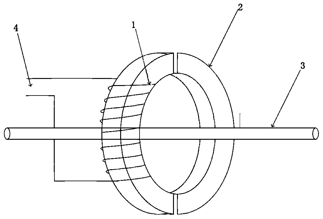
[0021] The wire CT energy harvesting unit is based on a magnetic core formed by stacking two semicircular annular silicon steel sheets 2 that can be cross-fitted closely, and a multi-turn secondary coil 1 is wound on the magnetic core, and the magnetic core is placed in the power transmission On the line body 3.

[0022] Since the current of the main body of the transmission line changes from time to time, the output power of the secondary side of the energy harvesting CT to the load also ...


PUM


Abstract

The invention relates to an energy supply system of an online monitoring device on a high-voltage transmission tower. The system comprises a wire CT energy taking unit, a laser energy transmission unit and an energy storage voltage stabilization unit which are connected in sequence. The wire CT energy taking unit is installed on a power transmission line body and comprises a secondary induction current processing loop, the secondary induction current processing loop is connected with a laser generator of the laser energy transmission unit, and the laser energy transmission unit comprises a laser generator, an energy transmission optical fiber and a photocell unit which are connected in sequence. The energy transmission optical fiber is arranged in an insulator, two optical fiber connectorsare respectively led out from the two sides of the insulator, a high-voltage side connector is connected with the laser generator, and a low-voltage side connector is connected with the photocell unit. The photocell unit receives the light energy outputted by the energy transmission optical fiber and converts the light energy into electric energy through a photoelectric effect. The energy supplysystem is stable and reliable in energy supply and long in service life and is capable of meeting the continuous energy supply requirement of higher-power online monitoring equipment.

Description

technical field [0001] The invention belongs to the field of high-voltage power transmission, and relates to a technology for monitoring the operation of high-voltage power transmission line equipment, in particular to an energy supply system for an online monitoring device on a high-voltage power transmission iron tower. Background technique [0002] At present, the sensors on the main body of the transmission line and the iron tower are mostly powered by solar panels, micro-wind generators, and batteries. The above-mentioned methods all face problems such as unstable energy supply and short life. Some scholars proposed to use electrostatic induction to arrange plates on the iron tower, relying on the capacitance between the line body and the plates to obtain energy, but faced with the problems of too small power and too large area of ​​the plates. Some scholars have proposed to use the induction current technology to directly obtain stable electric energy from the transmis...

Claims


Application Information

Patent Timeline
Patent Type & Authority Applications(China)
IPC IPC(8): H02J50/30H02J7/02H02J50/10
CPCH02J7/02H02J50/10H02J50/30
Inventor 辛晓虎王建慧欧干新肖建超武新松冯焕阳郭建涛孔晓利王宝恒孙执政王大成
Owner STATE GRID TIANJIN ELECTRIC POWER
Why Eureka
Try Eureka