Automatic temperature control carbon fiber heating deicing device of medium-low speed maglev transportation power supply rail

A technology of power supply rail and carbon fiber, which is applied in the direction of ohmic resistance heating parts, rail, track cleaning, etc. Ice phenomenon, effect of reducing operating costs

Inactive Publication Date: 2020-08-21
TONGJI UNIV +1
View PDF10 Cites 0 Cited by
  • Summary
  • Abstract
  • Description
  • Claims
  • Application Information

AI Technical Summary

Problems solved by technology

In the process of taking current from the side current receiver, it is greatly affected by the installation accuracy of the power supply contact rail and the smoothness of the track. In winter, the surface of the power supply rail is prone to icing due to rain, snow and low temperature, which will seriously affect the power supply performance. fall, affecting driving safety
[0003] Therefore, it is necessary to study an online temperature measurement and deicing device for the power supply rail of medium and low-speed maglev trains to avoid the problem of unstable current flow due to icing of the power supply rail and affect driving safety, thereby improving the reliability of the system

Method used


Image

  • Automatic temperature control carbon fiber heating deicing device of medium-low speed maglev transportation power supply rail
  • Automatic temperature control carbon fiber heating deicing device of medium-low speed maglev transportation power supply rail
  • Automatic temperature control carbon fiber heating deicing device of medium-low speed maglev transportation power supply rail

Examples


Embodiment 1

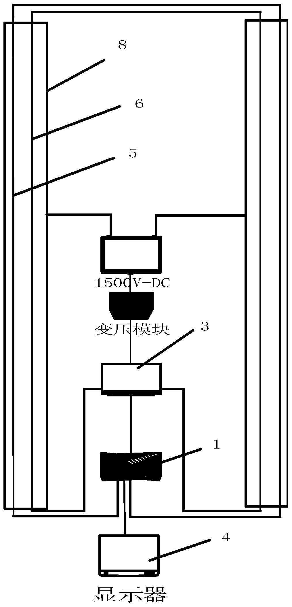
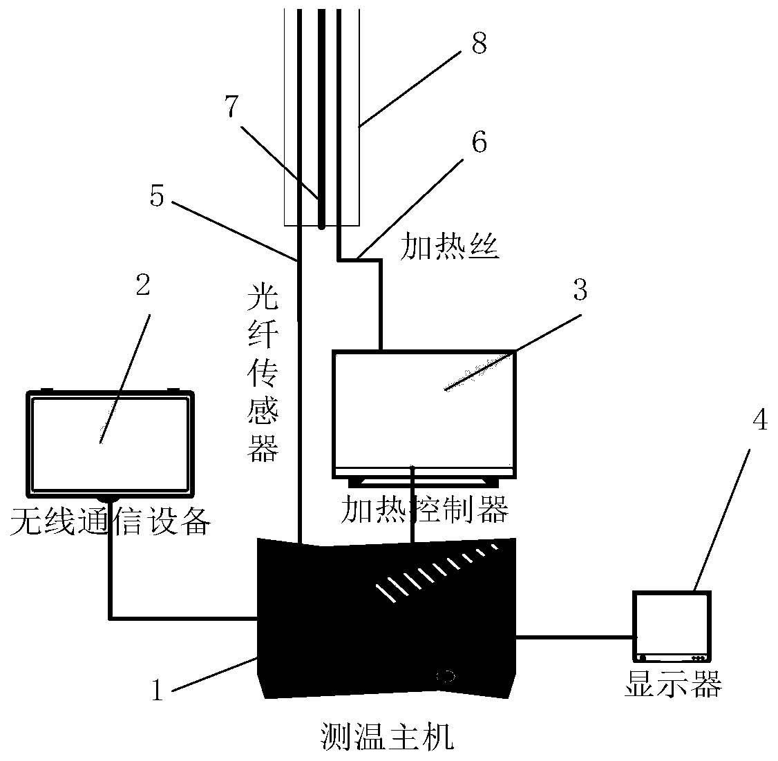
[0048] Such as figure 1 As shown, this example is used for a carbon fiber electric heating and deicing device for a medium-low speed maglev transportation power supply rail, including a distributed optical fiber temperature measurement component and a heating component. The distributed optical fiber temperature measurement component includes a temperature measurement host 1, an optical fiber sensor 5, a wireless communication Component 2, the temperature measurement host 1 is connected to the control center through the wireless communication component 2, and transmits temperature information in real time; the optical fiber sensor 5 adopts the spiral steel pipe armored temperature measurement optical cable commonly used in the market. The output end of the optical fiber sensor 5 is directly connected with the temperature measuring host 1 .

[0049] The temperature measurement host 1 is equipped with a display 4, the temperature measurement host is equipped with a windows operat...

Embodiment 2

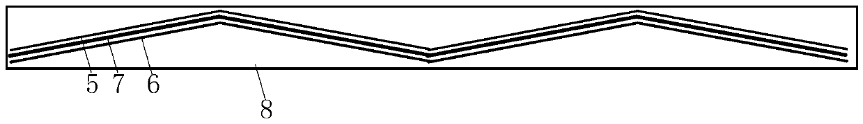
[0053] Such as Figure 4 , Figure 5 As shown, another form of power supply rail is characterized in that, on the basis of the existing Changsha medium and low-speed maglev train power supply rail, the lower part is provided with multiple card slots as required, and heating wire 6 and optical fiber sensor 5 are installed. The equipment is the same as in Example 1.


PUM


Abstract

The invention relates to an automatic temperature control carbon fiber heating and deicing device of a medium-low speed maglev transportation power supply rail. The device comprises a distributed optical fiber temperature measurement assembly, a wireless communication assembly and a heating assembly, wherein the distributed optical fiber temperature measurement assembly comprises mutually connected temperature measurement hosts and optical fiber sensors arranged in the power supply rail and used for measuring the temperature near a power supply line; the wireless communication assembly is connected with the temperature measurement hosts and a control center and used for transmitting temperature information; the heating assembly comprises a heating wire arranged in parallel with the power supply line and a heating controller which is connected with the temperature measuring host and provided with a relay, and the heating wire is connected with the heating controller. Compared with the prior art, the invention has the advantages of continuous, accurate and real-time measurement, suitability for high electromagnetic environment, remote monitoring, high supply sensitivity, long servicelife, low cost, high electric-thermal conversion efficiency, convenience in maintenance and the like.

Description

technical field [0001] The invention relates to the technical field of rail transit vehicles, in particular to an automatic temperature-controlling carbon fiber heating and deicing device for a medium-low speed maglev transportation power supply rail. Background technique [0002] Medium and low-speed maglev trains are driven by short-stator induction motors, and the induction motor stator installed on the train needs to be powered by the ground. At present, the power supply method of medium and low-speed maglev trains is: install a power supply contact rail on the side of the track beam under the F-shaped suspension guide rail, A lateral current collector is installed at the bottom of the suspension frame of the maglev train. Under a certain pressure, the side current collector sends the ground electric energy to the vehicle through mechanical sliding contact with the power supply contact rail. In the process of taking current from the side current receiver, it is greatly ...

Claims


Application Information

Patent Timeline
Patent Type & Authority Applications(China)
IPC IPC(8): E01H8/08E01B25/30H05B3/02G08B21/18
CPCE01B25/30E01H8/08G08B21/18H05B3/02
Inventor 潘洪亮唐少强邱宇杨颖佟来生张杨
Owner TONGJI UNIV
Why Eureka
Try Eureka