Gas pipeline leakage detection device and application method thereof

A leak detection device, gas pipeline technology, applied in the direction of measuring device, liquid tightness measurement using liquid/vacuum degree, pipe components, etc., can solve the problems of high cost and low detection accuracy

Inactive Publication Date: 2020-08-21
怀化新奥燃气有限公司
View PDF8 Cites 5 Cited by
  • Summary
  • Abstract
  • Description
  • Claims
  • Application Information

AI Technical Summary

Problems solved by technology

[0005] Therefore, the embodiment of the present invention provides a gas pipeline leakage detection device and its use method, aiming to solve the problems of low detection accuracy and high cost in the prior art

Method used


Image

  • Gas pipeline leakage detection device and application method thereof
  • Gas pipeline leakage detection device and application method thereof
  • Gas pipeline leakage detection device and application method thereof

Examples


Embodiment 1

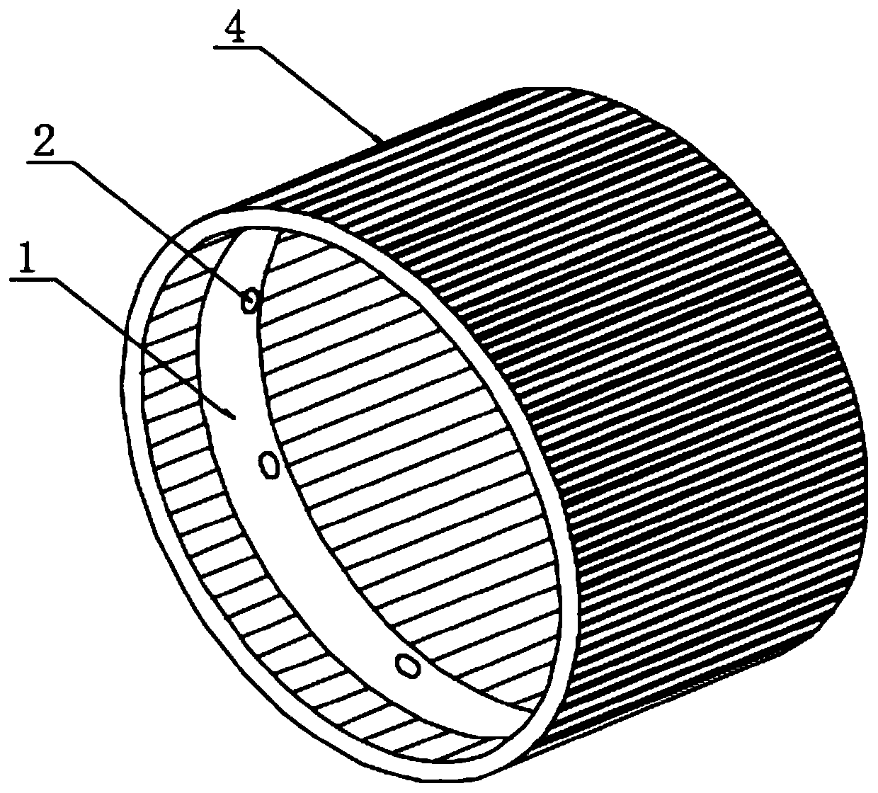
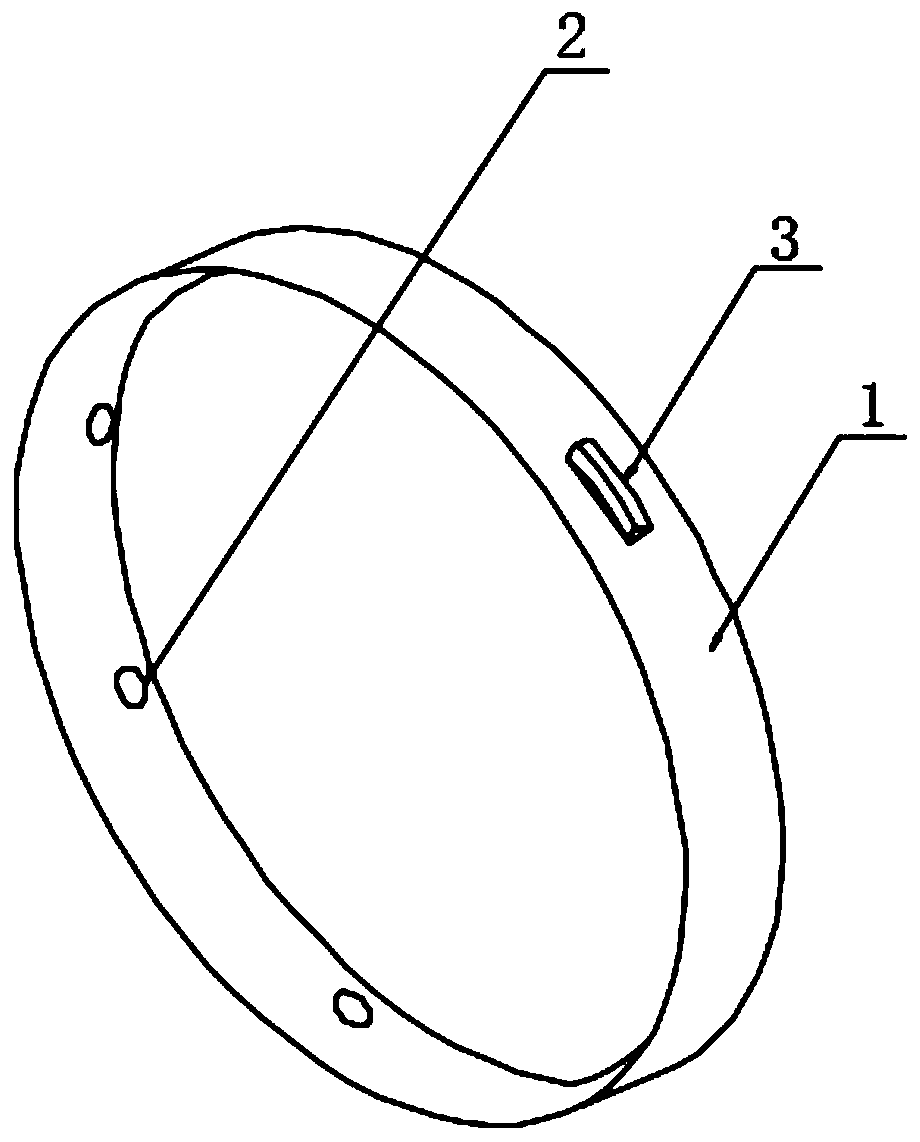
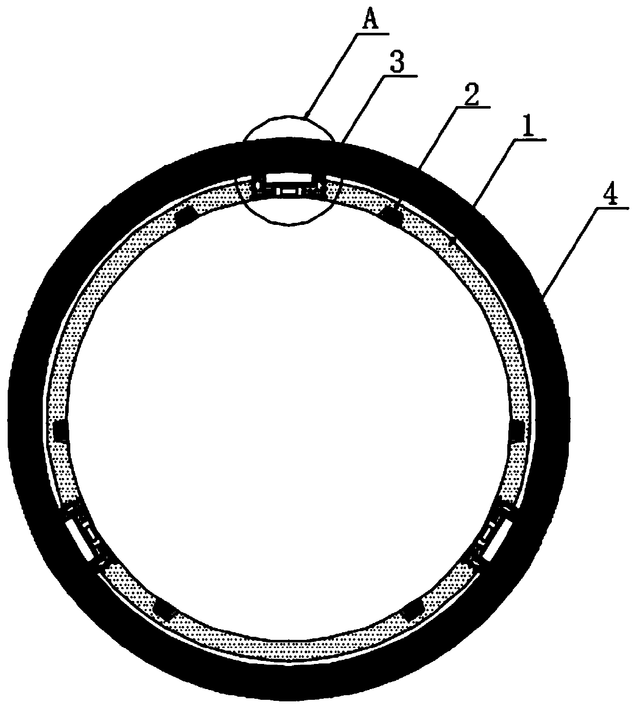
[0037] Refer to the attached Figure 1-7, a gas pipeline leakage detection device of this embodiment and its use method, the detection device is movably arranged in the gas pipeline 4, the detection device includes an annular shell 1, a plurality of detection components 2 and a plurality of drive mechanisms 3, multiple The two detection components 2 are evenly arranged on the inner wall of the annular casing 1, and the plurality of driving mechanisms 3 are evenly arranged on the outer wall of the annular casing 1 and are attached to the inner wall of the gas pipeline 4. Respectively drive the detection device to perform linear reciprocating motion in the gas pipeline 4, and the detection component 2 performs an all-round detection on the gas pipeline 4 during the reciprocating motion;

[0038] The detection assembly 2 includes an inner wall recess 21 and a sensor probe 22, a GPS locator 23 and a single-chip microcomputer 24 installed in the inner wall recess 21, the sensor pro...

Embodiment 2

[0051] Refer to the attached Figure 8-9 , the annular housing 1 is made up of three arc-shaped plates 8, and the three arc-shaped plates 8 form a circle, and each arc-shaped plate 8 is equipped with a driving mechanism 3 and a plurality of detection assemblies 2, and the arc-shaped plates 8 Both ends of the shaped plate 8 are provided with a T-shaped chute 9, and an arc-shaped slide bar 10 is arranged between two adjacent arc-shaped plates 8. Type chute 9 matches.

[0052] Further, both ends of the arc-shaped slide bar 10 are provided with a plurality of through-holes 11, and the end of the arc-shaped plate 8 corresponding to the through-holes 11 is provided with a mounting hole 12, and the through-hole 11 and the mounting hole 12 correspond to each other. Correspondingly, screws are provided outside the installation hole 12 , and the screws pass through the installation hole 12 and the through hole 11 to fix the arc-shaped sliding bar 10 and the arc-shaped plate 8 .

[005...


PUM


Abstract

The invention discloses a gas pipeline leakage detection device and an application method thereof, and in particular relates to the field of gas pipeline leakage detection. The detection device is arranged in a gas pipeline movably. The detection device comprises an annular housing, a plurality of detection assemblies and a plurality of driving mechanisms. The detection assemblies are uniformly arranged on the inner side wall of the annular housing in a surrounding manner, the driving mechanisms are uniformly arranged on the outer side wall of the annular housing in a surrounding manner and are attached to the inner wall of the gas pipeline, and the detection device is separately driven by gas conveying wind power and the driving mechanisms to move linearly in a reciprocating manner in thegas pipeline and detects the gas pipeline in the reciprocating motion process all around. The detection device detects a leakage condition by means of a plurality of groups of sensor probes accordingto pressure or flow. Matched with an angular sensor and a GPS positioner in use, the gas pipeline leakage detection device can find a gas pipeline leakage position quickly and precisely, so that workof exacting the leakage position again by maintenance staff in a later period is avoided. Quick repair can be further achieved, so that soil pollution is avoided.

Description

technical field [0001] The embodiments of the present invention relate to the field of gas pipeline leakage detection, in particular to a gas pipeline leakage detection device and a method for using the same. Background technique [0002] The gas content in the soil of the earth has a great influence on the growth of vegetation. At present, the urban greening area is mainly the street greening location. According to the requirements of the greening and environmental protection unit, the soil and soil gas content of the greening vegetation death were studied, and the cause of some vegetation death was found. It is closely related to methane, which is the main component of city gas. Leaked gas is mixed in soil gas through turbulence, mass flow, etc. in the process of urban gas transmission (relying on soil respiration takes several months to remove methane), causing local vegetation to die due to lack of oxygen. Conduct research on the problem of preventing gas leaks. [000...

Claims


Application Information

Patent Timeline
Patent Type & Authority Applications(China)
IPC IPC(8): F16L55/32F16L55/38G01M3/28G01S19/42F16L101/30
CPCF16L55/32F16L55/38F16L2101/30G01M3/2807G01M3/2815G01S19/42
Inventor 张书安曾学智曾晶
Owner 怀化新奥燃气有限公司
Why Eureka
Try Eureka