Water pollution treatment device capable of automatically replacing filter screen

A treatment device and automatic replacement technology, applied in the field of water pollution, can solve the problems of low water pollution treatment efficiency, difficult to separate targeted treatment, increased filtration difficulty, etc., to achieve high water pollution treatment efficiency, prolong effective filtration time, guarantee Continuously rising effect

Active Publication Date: 2020-08-25
FUYANG HUAHENG IND
View PDF6 Cites 2 Cited by
  • Summary
  • Abstract
  • Description
  • Claims
  • Application Information

AI Technical Summary

Problems solved by technology

Acids, alkalis, oxidants, and compounds such as copper, cadmium, mercury, and arsenic in sewage, as well as organic poisons such as benzene, dichloroethane, and ethylene glycol, will kill aquatic organisms and affect drinking water sources and scenic spots.
[0003] The current sewage treatment device does not process before filtration, the difficulty of filtration is greatly increased and the filtered matter is mixed together and it is difficult to treat them separately. The efficiency of water pollution treatment is low, and the filter screen of the sewage treatment device is not replaced for a long time. With the increase of usage time, the processing capacity of the device decreases, and the replacement of the filter screen of the device at this stage is very troublesome

Method used


Image

  • Water pollution treatment device capable of automatically replacing filter screen
  • Water pollution treatment device capable of automatically replacing filter screen
  • Water pollution treatment device capable of automatically replacing filter screen

Examples


Embodiment Construction

[0019] All features disclosed in this specification, or steps in all methods or processes disclosed, can be combined in any way, except for mutually exclusive features and or steps.

[0020] Combine below Figure 1-4 The present invention is described in detail, and for convenience of description, the orientations mentioned below are now stipulated as follows: figure 1 The up, down, left, right, front and back directions of the projection relationship itself are the same.

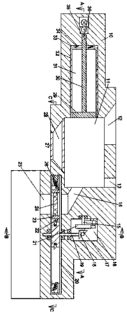
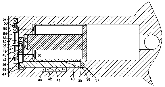
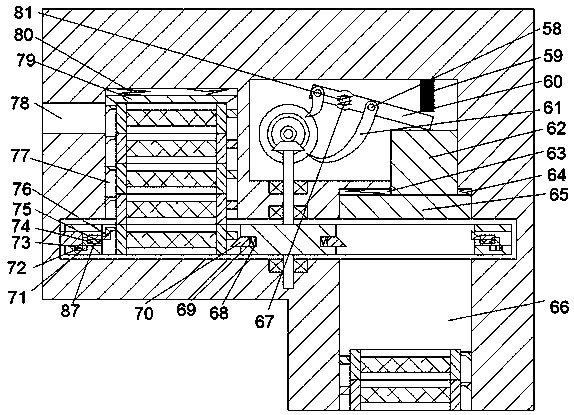
[0021] A water pollution treatment device that automatically replaces the filter screen of the device of the present invention includes a box body 10, the top wall of the box body 10 is provided with an inlet bucket groove 12 with an upward opening, and the top wall of the box body 10 is provided with an upward opening and The upper separation pipe 13 located on the right side of the inlet bucket 12, the bottom wall of the inlet bucket 12 and the upper separation pipe 13 is provided with a sedimentation se...


PUM


Abstract

The invention discloses a water pollution treatment device capable of automatically replacing a filter screen. The device comprises a box body, and an inlet hopper groove with an upward opening is formed in the top wall of the box body; an upper separation pipe with an upward opening is arranged on the top wall of the box body and is arranged on the right side of the inlet hopper groove; a precipitation separation cavity is formed between the inlet hopper groove and the bottom wall of the upper side separation pipe; a lower-layer discharge groove with a downward opening is formed in the bottomwall of the precipitation separation cavity; sealing plates are symmetrically arranged on the top wall and the bottom wall of the lower-layer discharge groove up and down; a hydraulic cylinder chutewith a rightward opening is formed in the left end wall of the precipitation separation cavity; a standing separation mechanism is arranged in the hydraulic cylinder chute; the right end wall of the precipitation separation cavity is fixedly connected with a middle-layer discharge pipe; a turntable cavity is formed in the bottom wall of the right end of the middle-layer discharge pipe, a disc is arranged in the turntable cavity, the disc is fixedly connected with a turntable shaft, and the turntable shaft is rotatably connected with the box body. Therefore, the filtering difficulty is greatlyreduced, filtered substances are separately collected, the water pollution treatment efficiency is relatively high, and the continuous improvement of the device treatment capacity is ensured.

Description

technical field [0001] The invention relates to the technical field related to water pollution, in particular to a water pollution treatment device for automatically replacing filter screens. Background technique [0002] Water pollution is water that reduces or loses the use value of water caused by harmful chemicals and pollutes the environment. Acids, alkalis, oxidants, and compounds such as copper, cadmium, mercury, and arsenic in sewage, organic poisons such as benzene, dichloroethane, and ethylene glycol, will kill aquatic organisms and affect drinking water sources and scenic spots. [0003] The current sewage treatment device does not perform treatment before filtration, the difficulty of filtration is greatly increased and the filtered matter is mixed together and it is difficult to treat them separately. The efficiency of water pollution treatment is low, and the filter screen of the sewage treatment device is not replaced for a long time. With the increase of the...

Claims


Application Information

Patent Timeline
IPC IPC(8): B01D36/04
CPCB01D36/04
Inventor 于建江
Owner FUYANG HUAHENG IND
Why Eureka
Try Eureka