
Heavy reduction withdrawal and straightening machine of billet caster, and withdrawal and straightening machine hydraulic control system and control method

A hydraulic control system and billet continuous casting technology, which is applied in the field of metallurgical equipment, can solve the problems of large hydraulic cylinder specifications of the tension leveler, increase in the size of the tension leveler equipment, and large pressing force of the tension leveler, so as to improve reliability. Performance and service life, prevention of side force, precise control of roll gap position

Pending Publication Date: 2020-08-25
CHINA NAT HEAVY MACHINERY RES INSTCO
View PDF0 Cites 0 Cited by
  • Summary
  • Abstract
  • Description
  • Claims
  • Application Information

AI Technical Summary

Problems solved by technology

[0003] The drawing and leveling machine of the billet continuous casting machine is usually controlled by one hydraulic cylinder of the drawing and leveling machine to realize the function of heavy reduction. Due to the heavy reduction process, the maximum reduction of a single roller is about 20mm, and the casting slab at the heavy reduction position has already solidification, so the compression force of the tension leveler is very large, which makes the specification of the hydraulic cylinder of the tension leveler required by the equipment also large, thereby increasing the size of the tension leveler equipment itself, and at the same time, one hydraulic cylinder of the tension leveler is easy to cause heavy pressure Slab deviation during down process

Method used


Image

  • Heavy reduction withdrawal and straightening machine of billet caster, and withdrawal and straightening machine hydraulic control system and control method
  • Heavy reduction withdrawal and straightening machine of billet caster, and withdrawal and straightening machine hydraulic control system and control method

Examples


Embodiment 1

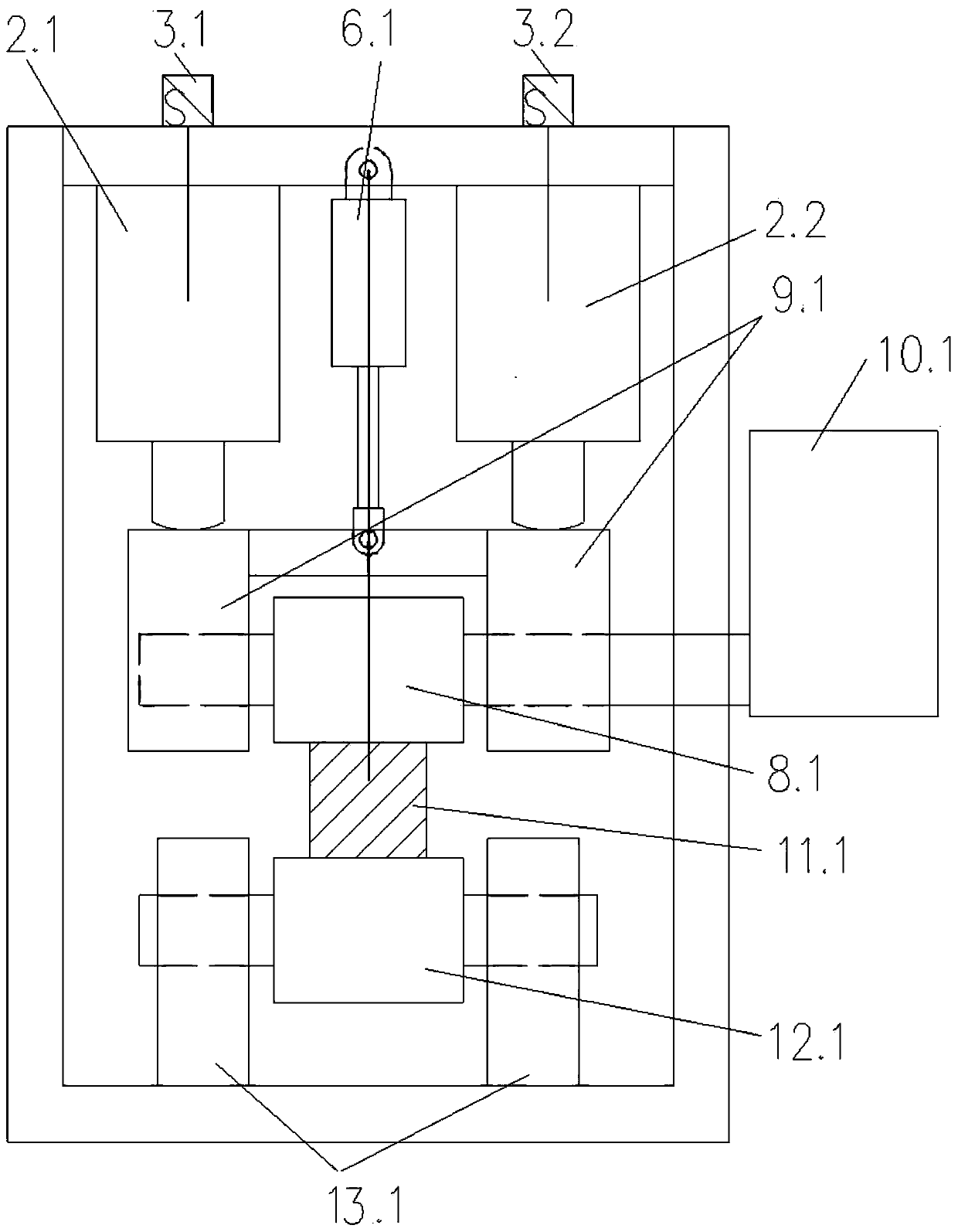
[0024] refer to figure 1 , is a structural schematic diagram of Embodiment 1 of the present invention, a billet continuous casting machine heavy-pressure pull-down leveler, at least including a pull-leveler frame, and the top of the inner side of the pull-leveler frame is connected to the billet continuous caster heavy-pressure pull-down leveler Machine hydraulic control system, the bottom of the inner side of the tension leveler frame is connected with two tension leveler lower roll bearing housings 13.1, the tension leveler lower roll bearing housings 13.1 are connected with the tension leveler lower roll 12.1, the tension leveler lower roll 12.1 is connected The top of the roll 12.1 is connected with the upper roll 8.1 of the tension leveler through the cast slab 11.1, the upper roll 8.1 of the tension leveler is connected by two bearing housings 9.1 of the upper roll of the tension leveler and is located in the middle of the frame of the tension leveler, and the upper roll ...

Embodiment 2

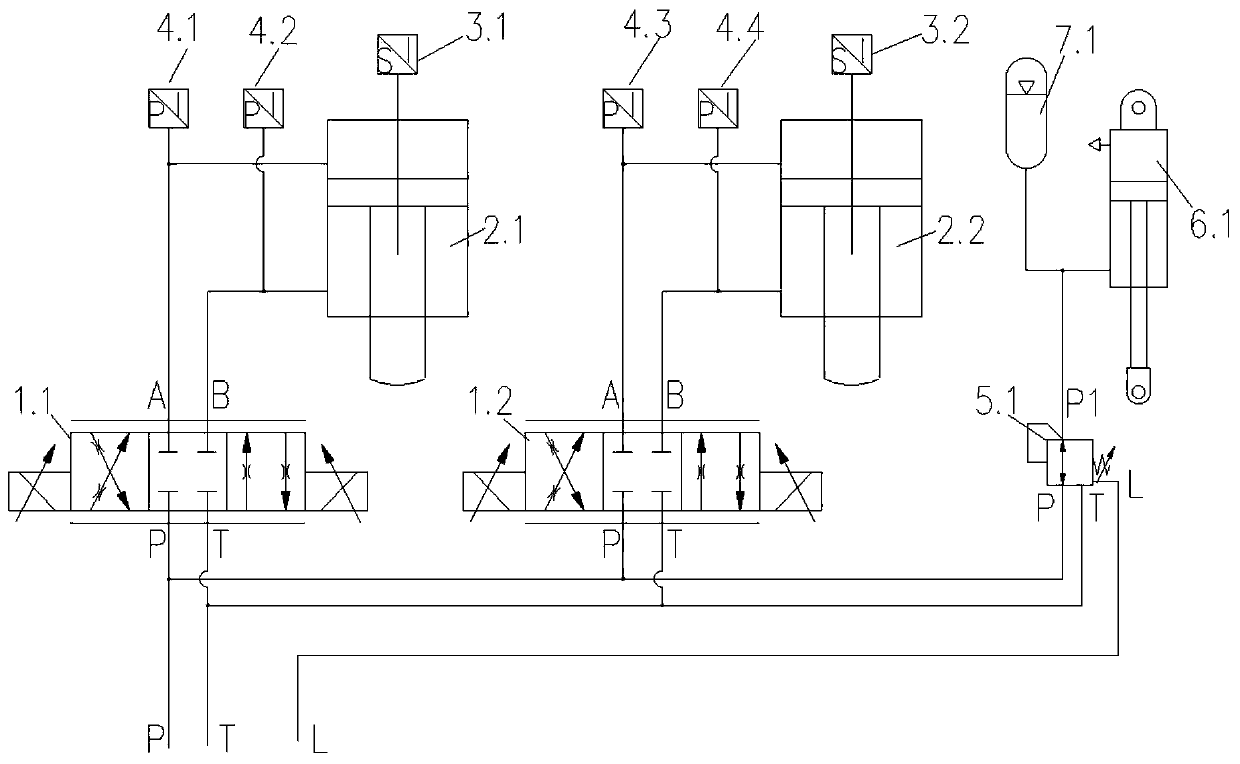
[0028] refer to figure 2, compared with Embodiment 1, the difference of this embodiment is that: a billet continuous casting machine heavy pressure pull-down straightening machine hydraulic control system, including proportional directional valve, stretching straightening machine servo hydraulic cylinder, three-way pressure reducing valve 5.1, balance cylinder 6.1, bladder type accumulator 7.1 and PLC control unit, the tail of the servo hydraulic cylinder of the tension leveler is connected to the top of the inner side of the tension leveler frame through a flange, and the end of the piston rod of the tension leveler servo hydraulic cylinder is Mushroom head type, the piston rod end of the servo hydraulic cylinder of the tension leveler contacts with the top of the upper roller bearing seat 9.1 of the tension leveler through the mushroom head, one end of the balance cylinder 6.1 is hinged with the top of the inner frame of the tension leveler, and the balance cylinder 6.1 The...

Embodiment 3

[0035] A hydraulic control method for a heavy-pressure pull-down straightener of a billet continuous caster includes the hydraulic control system for a heavy-pressure pull-down straightener of a billet continuous caster described in Embodiment 2, including the following steps:

[0036] Step 1: The transmission device 10.1 of the straightening machine drives the upper roll 8.1 of the straightening machine to rotate between the bearing seats 9.1 of the two upper rolls of the straightening machine. Rotate between the bearing housings 13.1 of the lower rollers of a tension leveling machine;

[0037] Step 2: The upper roll 8.1 of the tension leveler controls the servo hydraulic cylinder 2.1 of the first tension leveler, the servo hydraulic cylinder 2.2 of the second tension leveler and the balance cylinder through the PLC control unit in the hydraulic control system of the billet continuous casting machine. 6.1 Further control the roll gap position composed of the upper roll 8.1 of...


PUM


Abstract

The invention relates to the field of metallurgical equipment, in particular to a heavy reduction withdrawal and straightening machine of a billet caster, and a withdrawal and straightening machine hydraulic control system and control method. A displacement sensor is arranged in each withdrawal-and-straightening-machine servo hydraulic cylinder, and hydraulic loops of a piston cavity and a rod cavity of each servo hydraulic cylinder are connected with pressure sensors respectively. The two withdrawal-and-straightening-machine servo hydraulic cylinders are used for controlling the lifting and down pressing of an upper roller of the heavy reduction withdrawal and straightening machine, a heavy reduction balance cylinder is used for lifting the upper roller of the withdrawal and straighteningmachine, the heavy reduction balance cylinder adopts the pressure reduced by connecting the rod cavity with a three-way pressure reducing valve, the pressure of the three-way pressure reducing valveis set, it is guaranteed that the upper roller of the heavy reduction withdrawal and straightening machine makes tight contact with the piston rod ends of the two withdrawal-and-straightening-machineservo hydraulic cylinders all the time, the pressure sensors are used for compensating for equipment gaps and equipment deformation in the working process of the heavy reduction withdrawal and straightening machine, and the needed equipment control precision is achieved.

Description

technical field [0001] The invention relates to the field of metallurgical equipment, in particular to a heavy-pressure down-draw leveler for a billet continuous casting machine, a hydraulic control system and a control method for the draw-leveler. Background technique [0002] The internal quality problems of internal center segregation, center porosity and shrinkage cavity are common in billet continuous casting machines, resulting in certain quality defects of continuous casting slabs. Continuous casting machine light reduction technology can effectively solve the problem of internal center segregation of continuous casting slabs. However, little effect has been achieved for the problems of porosity and shrinkage cavities inside the continuous casting slab. In order to solve the problems of looseness and shrinkage cavity inside the continuous casting slab, a continuous casting production process under heavy pressure with high continuous casting quality and high production...

Claims


Application Information

Patent Timeline
Patent Type & Authority Applications(China)
IPC IPC(8): B22D11/12B22D11/16
CPCB22D11/1226B22D11/16
Inventor 李向辉张伟李生斌李积文
Owner CHINA NAT HEAVY MACHINERY RES INSTCO
Learn More