
Stress relieving, dehumidifying and ventilating method and structure for external wall insulation

A technology for thermal insulation and stress release of external walls, applied in thermal insulation, building components, building structures, etc., to control cracks, improve thermal insulation and energy-saving effects, and maintain thermal insulation and energy-saving effects.

Pending Publication Date: 2020-08-25
上海天补科技有限公司
View PDF0 Cites 0 Cited by
  • Summary
  • Abstract
  • Description
  • Claims
  • Application Information

AI Technical Summary

Problems solved by technology

[0004] One of the technical problems to be solved by the present invention is to provide a thermal insulation system that eliminates cracking, leakage, reduction of thermal insulation effect, delamination of the decorative layer and anti-crack protective layer for the problems existing in the existing external wall thermal insulation system. Falling off, indoor condensation and mildew and other safety hazards, external wall insulation to improve living comfort, release stress, dehumidification and ventilation treatment methods
[0005] One of the technical problems to be solved by the present invention is to provide a thermal insulation system that eliminates cracking, leakage, reduction of thermal insulation effect, delamination of the decorative layer and anti-crack protective layer for the problems existing in the existing external wall thermal insulation system. Safety hazards such as shedding, indoor condensation and mildew, etc., external wall insulation to improve living comfort, release stress, dehumidification and ventilation treatment structure

Method used


Image

  • Stress relieving, dehumidifying and ventilating method and structure for external wall insulation
  • Stress relieving, dehumidifying and ventilating method and structure for external wall insulation

Examples


Embodiment Construction

[0031] The present invention will be further described below in conjunction with the accompanying drawings and specific embodiments.

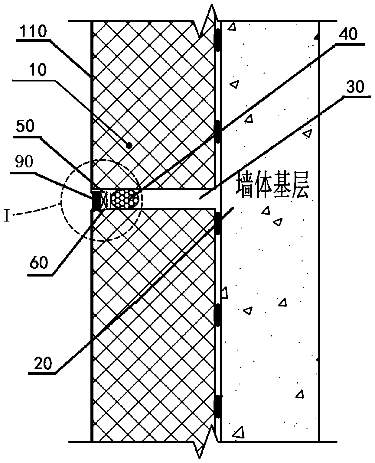
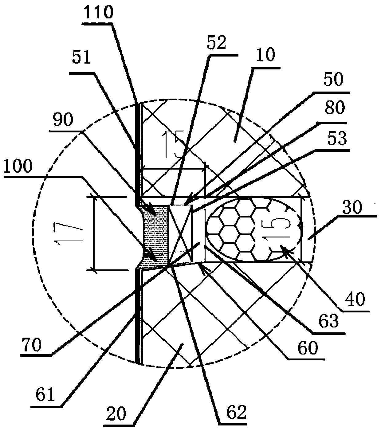
[0032] see figure 1 and figure 2 , a method for releasing stress, dehumidification and ventilation of external wall insulation of the present invention, comprising the following steps:

[0033] Step 1: Mark the positions of the stress relief joints 30 on the base wall 20 of the exterior wall or on the surface layer 110 of the exterior wall; Set a stress relief joint 30 not larger than the second floor;

[0034] Step 2: Reserving or cutting the stress relief seam 30 at the mark of the spring line, the depth of the stress relief seam 30 reaches part of the insulation layer 10 or to the base wall 20 of the outer wall;

[0035] Step 3: install the foam rod 40 in the stress relief seam 30; the foam rod 40 is pressed into an elliptical shape, so that the moisture in the humidity will be absorbed by the foam rod 40 during ventilation

[0036] Ste...


PUM


Abstract

The invention discloses a stress relieving, dehumidifying and ventilating method for external wall insulation. The method comprises the following steps of S1, marking a position where a stress reliefjoint is arranged; S2, reserving or cutting the stress relief joint in a snapline mark, wherein the stress relief joint penetrates part of an insulation layer or a base wall of an external wall in depth; S3, mounting a foam rod in the stress relief joint; S4, mounting a lower member in the stress relief join; S5, mounting an upper member in the stress relief join, wherein a zigzag ventilating channel which deforms by relieving stress is formed between the upper member and the lower member; S6, filling a gap between the upper member and the lower member with a sealant and forming a ventilatinghole in connection of the sealant and the lower member, wherein the ventilating hole communicates the ventilating channel to outer side; S7, adhering a waterproof adhesive tape to the upper member, the lower member and the sealant; and S8, carrying out surface decoration. The invention further discloses a stress relieving, dehumidifying and ventilating structure for external wall insulation.

Description

technical field [0001] The invention belongs to the fields of building energy saving, humidity control technology and exterior wall repair, and more specifically relates to a treatment method and structure for heat preservation, stress release, dehumidification and ventilation of exterior walls. Background technique [0002] If the insulation layer is not added in the residential, underground and other spaces, it will cause a serious loss of heat or cooling in the space, which will not only cause a waste of energy, but also reduce the comfort of personnel. Since the energy crisis, foreign developed countries have attached great importance to this issue. Many building spaces have used insulation layers to reduce energy consumption of building enclosures and improve personnel comfort. However, energy conservation has been compulsory for residential buildings in China for a long time, and external wall insulation has been widely used. The external thermal insulation structure ...

Claims


Application Information

Patent Timeline
Patent Type & Authority Applications(China)
IPC IPC(8): E04B1/76E04B1/70
CPCE04B1/70E04B1/7015E04B1/76E04B1/762
Inventor 缪德忠杨雨奕
Owner 上海天补科技有限公司
Learn More