A linkage control method for oilfield water source wells and water supply and injection stations

A technology for water source wells and oil fields, which is applied in pump control, earthwork drilling and production, wellbore/well components, etc., to achieve good effect, low power consumption, and easy promotion and use

Active Publication Date: 2021-03-05
宁夏铭盛能源科技有限公司
View PDF0 Cites 0 Cited by
  • Summary
  • Abstract
  • Description
  • Claims
  • Application Information

AI Technical Summary

Problems solved by technology

[0003] The technical problem to be solved by the present invention is to provide a linkage control method between the oilfield water source well and the water supply and injection station in view of the above-mentioned deficiencies in the prior art, which uses the vent solenoid valve on the vent pipe to pre-discharge the air in the pipe to avoid the backflow of the water source well. When the electric submersible pump is started, the starting current is too large, which leads to the problem that the electric submersible pump cannot be started. The frequency converter is used to control the electric submersible pump, which saves electricity and energy. Squeeze the air in the pipe, reduce the pressure in the pipe, use the three-phase electric parameter acquisition module to detect the fault of the electric submersible pump, and the control units of multiple water source wells work together according to the water level in the water storage tank, which has high efficiency and is easy to promote and use

Method used


Image

  • A linkage control method for oilfield water source wells and water supply and injection stations
  • A linkage control method for oilfield water source wells and water supply and injection stations
  • A linkage control method for oilfield water source wells and water supply and injection stations

Examples


Embodiment Construction

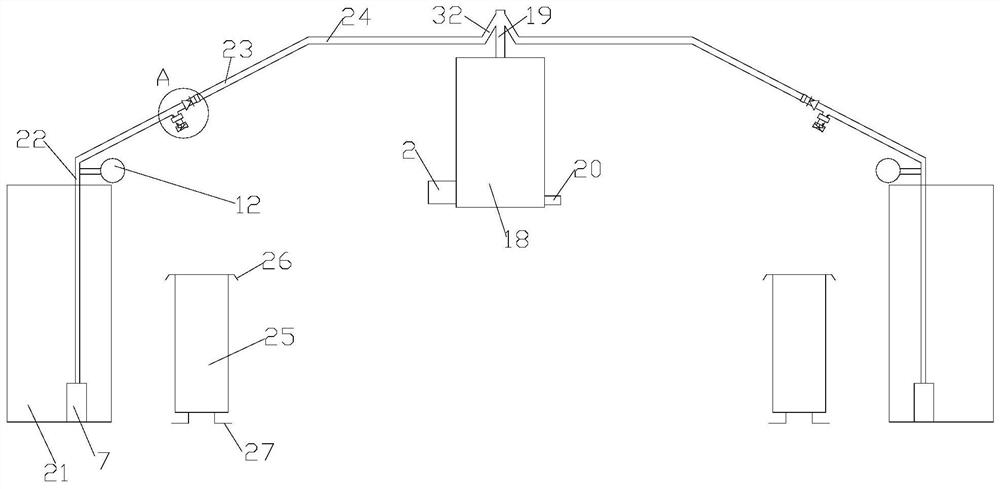
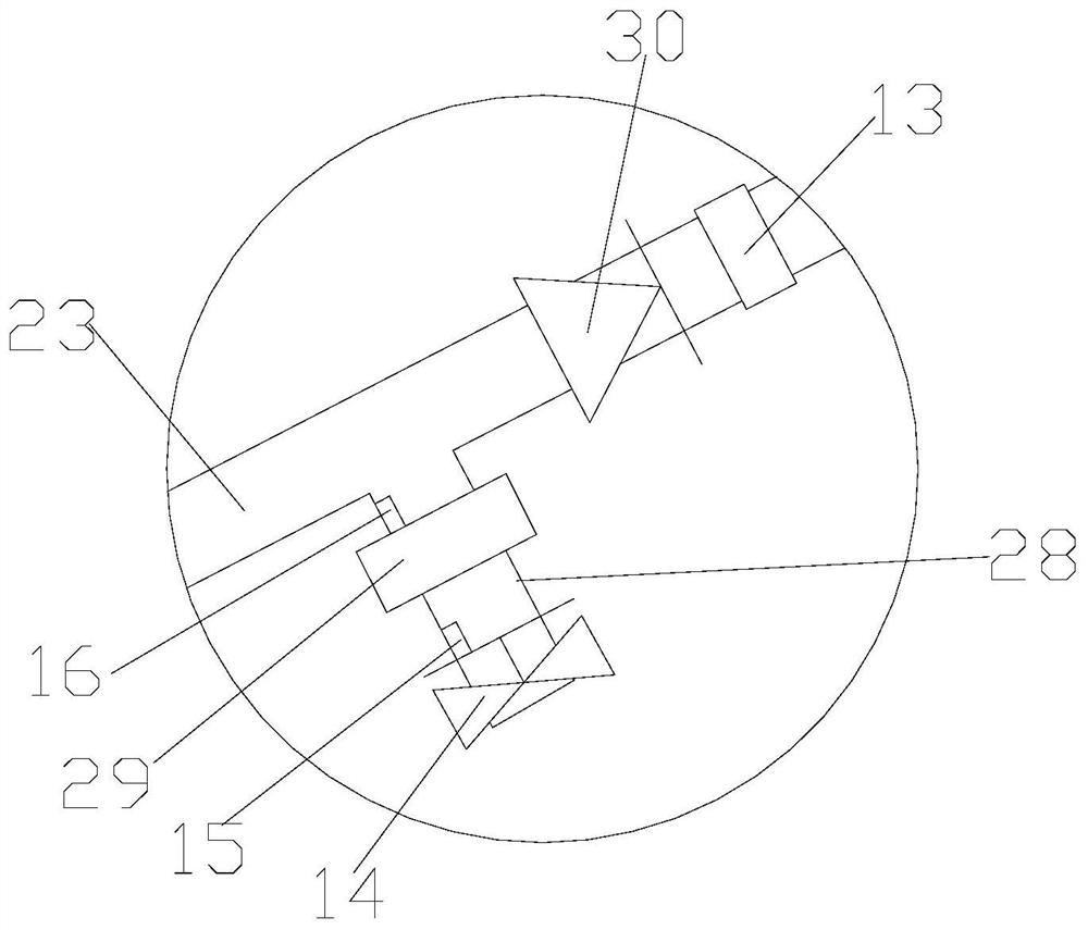
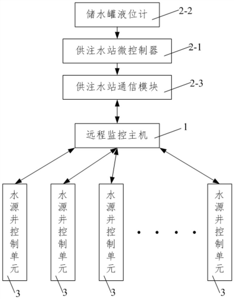
[0053] like Figure 1 to Figure 5 As shown in the present invention, a linkage control method between an oil field water source well and a water supply and injection station, the water source well control unit 3 for controlling the water output of the corresponding water source well 21 is arranged outside the water source well, and the water supply and injection station includes a water storage tank 18 and the water supply and injection station control terminal 2 for monitoring the change of the liquid level of the water storage tank 18, the number of the water source well control unit 3 is equal to the number of water source wells 21 and one-to-one correspondence, the water supply and injection station control terminal 2 and the water source well The control units 3 all communicate with the remote monitoring host 1, and the control terminal 2 of the water supply and injection station includes a microcontroller 2-1 of the water supply and injection station and is connected to t...


PUM


Abstract

The invention discloses a linkage control method for water source wells and a water supply and injection station of an oil field. The method comprises the following steps that 1, the first water source well is started to supply water to a water storage tank; 2, the second water source well is additionally arranged to supply water to the water storage tank; and 3, the liquid level change of the water storage tank is monitored in real time to increase or decrease water supply of the water source wells. According to the linkage control method, air in a pipe is discharged in advance through an emptying electromagnetic valve on an emptying pipe, and the problem that the back pressure of well mouths of the water source wells is large, and the starting current is too large when an electric submersible pump is started, so that the electric submersible pump cannot be started is solved; the electric submersible pump is controlled through a frequency converter, and thus electricity and energy aresaved; an inclined connecting water pipe and a check valve are matched to accumulate water flow, the air in the pipe is squeezed out, and the pressure in the pipe is reduced; and a three-phase electric parameter acquisition module is used for detecting the fault of the electric submersible pump, a plurality of water source well control units work cooperatively in a linkage mode according to the water level in the water storage tank, and thus the efficiency is high.

Description

technical field [0001] The invention belongs to the technical field of linkage control between an oilfield water source well and a water supply and injection station, and in particular relates to a linkage control method for an oilfield water source well and a water supply and injection station. Background technique [0002] Using water injection equipment to inject qualified water from water injection wells into the oil layer to maintain the pressure of the oil layer, this process is called oilfield water injection. Oilfield water injection is one of the important means to replenish energy to the formation and improve oil recovery in the process of oilfield development. The level of water injection well management technology determines the quality of oilfield development, and also determines the length of oilfield development life. The existing oilfield water source wells and water supply and injection station linkage management is not standardized, well workover on-site su...

Claims


Application Information

Patent Timeline
Patent Type & Authority Patents(China)
IPC IPC(8): E21B43/20E21B47/00F04D13/08F04D15/00
CPCE21B43/20E21B47/00F04D13/08F04D15/00F04D15/0088
Inventor 陈云刘大兴卢刚尉婷婷
Owner 宁夏铭盛能源科技有限公司
Why Eureka
Try Eureka