
Full-automatic compressed air supplying system and control method

A compressed air, fully automated technology, applied in the direction of pump control, pipeline system, container filling method, etc., can solve the problems of low efficiency, no air pressure detection parts, time-consuming and labor-intensive problems, so as to reduce the number of starts and stops, improve operation efficiency, extend The effect of longevity

Pending Publication Date: 2020-08-25
成都英派尔新能源科技有限公司
View PDF0 Cites 1 Cited by
  • Summary
  • Abstract
  • Description
  • Claims
  • Application Information

AI Technical Summary

Problems solved by technology

[0003] The system dedicated to providing compressed air becomes a compressed air supply system. In applications with higher requirements, the traditional compressed air supply system includes an air compressor, a check valve, a filter, a dryer and an air storage tank connected in sequence. Among them, there is only one air storage tank, and the start and stop control of the air compressor is manually controlled, or electric control is used but there is no air pressure detection component, and a fully automatic control system cannot be formed, so there are the following defects: if there is a power failure or air compressor failure, etc. , the compressed air in an air storage tank will be used up soon, and the on-site air source supply is not guaranteed, which affects the progress of industrial operations; when there is electricity, the air compressor starts and stops frequently, and manual operation is required to start and stop the air compressor. Time-consuming, laborious and inefficient

Method used


Image

  • Full-automatic compressed air supplying system and control method
  • Full-automatic compressed air supplying system and control method

Examples


Embodiment Construction

[0022] The present invention will be further described below in conjunction with accompanying drawing:

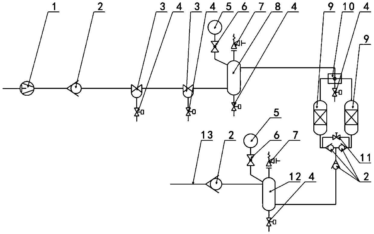
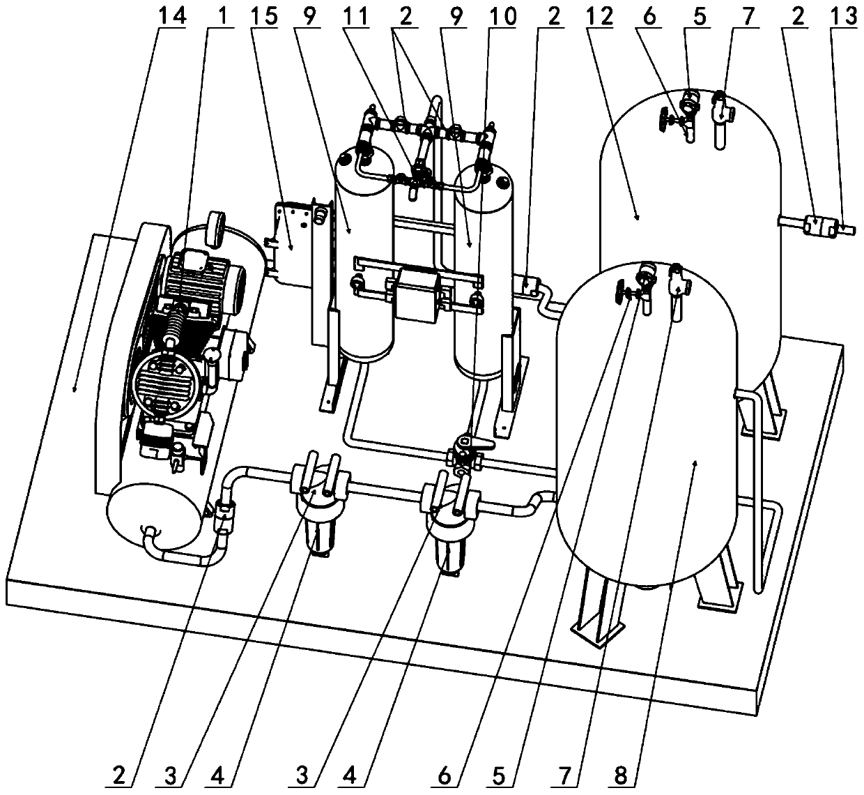
[0023] Such as figure 1 and figure 2 As shown, the fully automated compressed air supply system of the present invention includes an air compressor 1, five check valves 2, two filters 3, five sewage solenoid valves 4, and two ball valves 6 connected in series through air pipes. , two safety valves 7, a four-way valve 10, two dryers 9, a first gas storage tank 8, a second gas storage tank 12, two pressure transmitters 5 and a controller (not shown in the figure), The outlet of the air compressor 1 is connected to the inlet of the first filter 3, the outlet of the first filter 3 is connected in series with the second filter 3 and then connected to the inlet of the first air storage tank 8, and the first air storage The outlet of the tank 8 is connected to the inlet of the four-way valve 10, and the outlet of the four-way valve 10 is connected to the inlets of two dryers 9 ...


PUM


Abstract

The invention discloses a full-automatic compressed air supplying system. The full-automatic compressed air supplying system comprises an air compressor, a filter, a dryer and two air storage tanks which are mutually connected in series through air pipes, and further comprises two pressure transmitters and a controller, wherein the two pressure transmitters are installed on the two air storage tans respectively, and the two pressure transmitters and the air compressors are connected with the controller correspondingly. The invention further discloses a control method for the full-automatic compressed air supplying system. Firstly, whether the air pressure of the two air storage tanks reaches the upper limit is judged; then, whether there is a need for normal sewage discharging is judged; and finally, under the conditions that the air pressure of the two air storage tanks reaches the upper limit and the normal sewage discharging work is completed, the air compressor is stopped. By meansof the full-automatic compressed air supplying system and the control method thereof, a more sufficient air source can be provided during power failure or when the air compressor fails temporality, the air pressure of the air storage tanks and the air compressor can be monitored any time when there is electricity, it is ensured that the two air storage tanks are full of high-pressure air anytime,and automatic control is completely realized.

Description

technical field [0001] The invention relates to a compressed air supply system, in particular to a fully automatic compressed air supply system and a control method. Background technique [0002] Compressed air, that is, high-pressure air, is widely used in industry. For occasions with low requirements, it is only necessary for the air compressor to generate compressed air and deliver it to related equipment, such as compressed air for sewage treatment aeration; for occasions with high requirements , the compressed air generated by the air compressor needs to be filtered, dried and then delivered to related equipment, such as compressed air for industrial instruments or compressed air for pneumatic actuators. [0003] The system dedicated to providing compressed air becomes a compressed air supply system. In applications with higher requirements, the traditional compressed air supply system includes an air compressor, a check valve, a filter, a dryer and an air storage tank ...

Claims


Application Information

Patent Timeline
Patent Type & Authority Applications(China)
IPC IPC(8): F17C5/06F17C7/00F17C13/02F17C13/04F17D1/07F17D3/14F17D3/01F04B41/02F04B49/06
CPCF04B41/02F04B49/065F17C5/06F17C7/00F17C13/025F17C13/04F17C2201/0109F17C2201/032F17C2205/0302F17C2205/0323F17C2205/0326F17C2205/0341F17C2205/0352F17C2205/0388F17C2221/031F17C2225/0123F17C2227/0157F17C2227/044F17C2227/046F17C2250/01F17C2250/032F17C2250/043F17C2250/072F17C2260/013F17C2260/021F17C2265/012F17C2270/05F17D1/07F17D3/01F17D3/145
Inventor 马骞史斌彭清明史诚邵靖
Owner 成都英派尔新能源科技有限公司
Learn More