
A calibration method of spherical near-field antenna measurement system

A technology for measurement systems and near-field antennas, applied in radio wave measurement systems, antenna radiation patterns, instruments, etc., can solve the problems of investing in special equipment, spending a lot of time and labor costs, and difficult to meet the large-scale calibration requirements of measurement systems , to achieve the effect of reducing technical difficulty and high measurement accuracy

Active Publication Date: 2022-08-09
CHINA ELECTRONIC TECH GRP CORP NO 38 RES INST
View PDF8 Cites 0 Cited by
  • Summary
  • Abstract
  • Description
  • Claims
  • Application Information

AI Technical Summary

Problems solved by technology

[0004] The technical problem to be solved by the present invention is: how to solve the need to invest in special equipment during the calibration of the existing measurement system, the need to adjust the calibration parameters for different measurement systems, the need to spend a lot of time and labor costs, and it is difficult to meet the large-scale calibration of the measurement system Requirements and other issues, a spherical near-field antenna measurement system is provided

Method used


Image

  • A calibration method of spherical near-field antenna measurement system
  • A calibration method of spherical near-field antenna measurement system
  • A calibration method of spherical near-field antenna measurement system

Examples


Embodiment Construction

[0061] The embodiments of the present invention are described in detail below. This embodiment is implemented on the premise of the technical solution of the present invention, and provides a detailed implementation manner and a specific operation process, but the protection scope of the present invention is not limited to the following implementation. example.

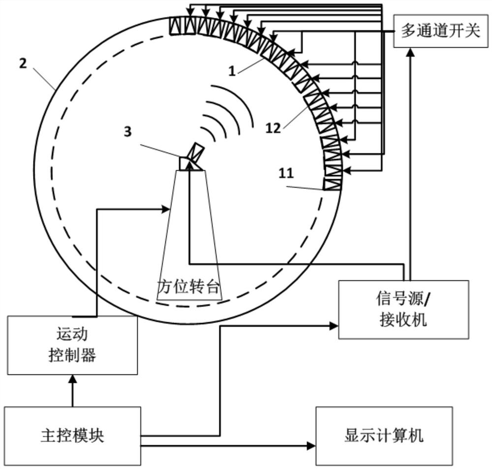
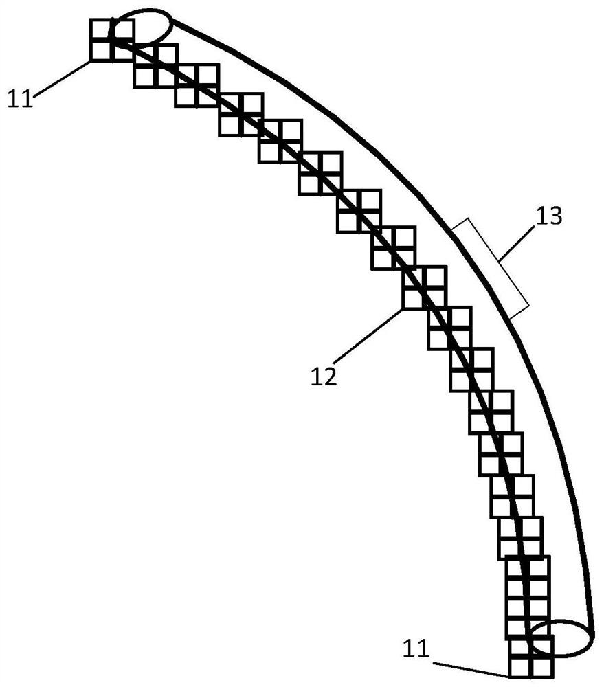
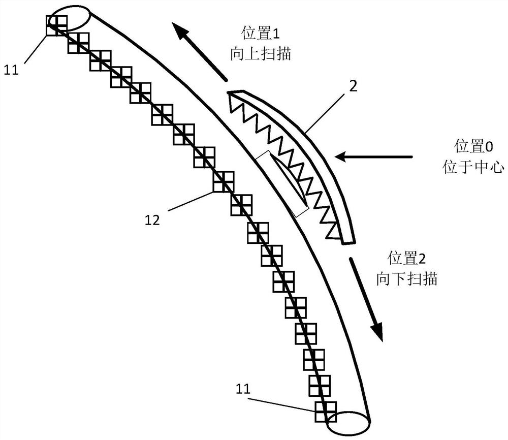
[0062] like Figures 1 to 3 As shown, this embodiment provides a technical solution: a spherical near-field antenna measurement system, including a main control module, a motion controller, a receiver, an elevation scan frame 2, a probe array 1, an azimuth turntable, a multi-channel switch, a calibration Antenna 3, the main control module is respectively connected with the elevation scan frame 2 and the azimuth turntable through the motion controller, the calibration antenna 3 is installed on the azimuth turntable, the main control module, the azimuth turntable The receiver, the multi-channel switch, and the probe ar...


PUM


Abstract

The present invention disclosed a correction method of a spherical near -field antenna measurement system. It belongs to the field of antenna measurement technology. The antenna measurement system includes the main control module, motion controller, receiver, pitch scanning rack, probe array, positioning, multi -channel switch, multi -channel switch, Correct the antenna, when the probe array is corrected, the corrected antenna emit signal, through space transmission, reach the probe array, and collect the correction data from the probe antenna in the probe array.Scan up to position 1, and collect the correction data to D again; scan down from the pitch scanning rack to the position 2, and collect the correction data to F again. Three sets of correction data are calculated to obtain a set of correction coefficients, and the coefficient is loaded to the near field to the field.Measure the software and automatically modify the measurement data during the test.The correction accuracy of the invention is high, the correction cost is low, and the correction speed is fast. It provides a new and efficient solution for the problem of multi -probe correction of the sphere.

Description

technical field [0001] The invention relates to the technical field of antenna measurement, in particular to a calibration method for a spherical near-field antenna measurement system. Background technique [0002] The multi-probe spherical near-field antenna measurement system is an effective antenna measurement device, which is widely used in various antenna testing fields such as communication antennas, phased array radar antennas, and reflector satellite antennas. The multi-probe spherical near-field antenna measurement system can complete the measurement of the antenna gain, pointing angle, lobe width, side lobe level and other technical indicators. [0003] During the use of this type of measurement system, the probe array needs to be periodically calibrated for amplitude and phase to ensure that the amplitude loss and phase delay of each channel are the same. At this stage, the calibration of the probe array needs to use some special equipment to complete, including ...

Claims


Application Information

Patent Timeline
Patent Type & Authority Patents(China)
IPC IPC(8): G01R29/10G01S7/40
CPCG01R29/10G01S7/4026G01S7/4004
Inventor 张重阳黄文涛张再庆陈旭刘浩明章健盛永鑫
Owner CHINA ELECTRONIC TECH GRP CORP NO 38 RES INST
Learn More