Compact large-view-field small F # catadioptric optical system

A technology with an optical system and a large field of view, applied in optics, optical components, instruments, etc., can solve the problems of a wide working band and a large imaging field of view, achieve a wide working spectrum, a large imaging field of view, and reduce the total number of lenses. effect of quantity

Pending Publication Date: 2020-08-25
XI'AN INST OF OPTICS & FINE MECHANICS - CHINESE ACAD OF SCI
View PDF1 Cites 3 Cited by
  • Summary
  • Abstract
  • Description
  • Claims
  • Application Information

AI Technical Summary

Problems solved by technology

[0005] The purpose of the present invention is to provide a compact large field of view small F# catadioptric optical system to solve the problem that the existing remote sensing optical system cannot simultaneously meet the requirements of large imaging field of view, wide working wavelength band and compact structure

Method used


Image

  • Compact large-view-field small F # catadioptric optical system
  • Compact large-view-field small F # catadioptric optical system
  • Compact large-view-field small F # catadioptric optical system

Examples


Embodiment Construction

[0026] The present invention will be further described below in conjunction with the accompanying drawings and specific embodiments.

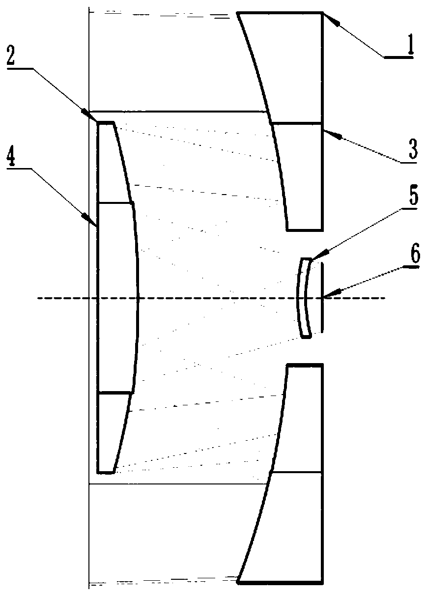
[0027] like figure 1 As shown, it is a schematic structural diagram of the optical system of this embodiment. The combined mirror of the primary mirror 1 and the third mirror 3, the combined mirror of the secondary mirror 2 and the fourth mirror 4, and the compensation lens 5 are placed on the optical path.

[0028] The axial center of the primary mirror 1 is provided with an inner hole, the three mirrors 3 are embedded in the inner hole of the primary mirror, and the outer peripheral surfaces of the three mirrors are close to the wall of the inner hole of the primary mirror; the axial center of the secondary mirror 2 is provided with an inner hole. The mirror 4 is embedded in the inner hole of the secondary mirror 2, and the outer peripheral surface of the fourth mirror 4 is close to the inner hole wall of the secondary mirror 2; the axial cen...


PUM


Abstract

The invention belongs to the field of optical imaging, and relates to a compact large-view-field small F # catadioptric optical system. The method is mainly used for large-view-field high-resolution earth imaging. The problem that an existing remote sensing optical system cannot meet the requirements for a large imaging view field, a wide working band and a compact structure at the same time is solved. The system sequentially comprises a primary mirror, a secondary mirror, a third mirror, a fourth mirror and a compensation lens in the light propagation direction. Inner holes are formed in theaxial centers of the primary mirror, the secondary mirror and the third mirror; the third mirror is embedded into the inner hole of the primary mirror; the fourth lens is embedded into an inner hole of the secondary lens; light is reflected by the primary mirror, the secondary mirror, the third mirror and the fourth mirror in sequence in the propagation direction and then penetrates through the compensation lens to reach a focal plane for imaging. The primary mirror, the secondary mirror, the third mirror and the fourth mirror are all even-order aspheric mirrors with the highest number of times being four; the four even-order aspheric reflectors are adopted to turn back a light path, and the total length of the system is greatly reduced; the primary mirror, the third mirror, the secondarymirror and the fourth mirror are integrally machined; the total number of lenses of the system is reduced, and system adjustment difficulty is lowered.

Description

technical field [0001] The invention belongs to the field of optical imaging, in particular to a compact large field of view and small F# catadioptric optical system. It is mainly used for large-field-of-view and high-resolution ground imaging, and can also be used in urban security monitoring, land census, disaster prevention and mitigation, and other fields. Background technique [0002] With the development of optical technology, the importance of the field of optical remote sensing has been increasing, and at the same time, higher performance requirements have been put forward for optical systems used in remote sensing. In order to meet the new performance requirements, the remote sensing optical system is gradually developing in the direction of long focal length, large aperture, wide spectral range, large field of view, and compact structure, and the total reflection system has unique advantages in achieving the above indicators. The traditional RC system has the adva...

Claims


Application Information

Patent Timeline
Patent Type & Authority Applications(China)
IPC IPC(8): G02B17/08
CPCG02B17/084G02B17/0844
Inventor 沈阳王虎金阿敏薛要克解永杰刘阳林上民刘杰刘美莹
Owner XI'AN INST OF OPTICS & FINE MECHANICS - CHINESE ACAD OF SCI
Why Eureka
Try Eureka