Chip pickling device

A pickling device and chip technology, which is applied in the direction of electrical components, semiconductor/solid-state device manufacturing, circuits, etc., can solve the problems of small contact area, poor pickling effect, and low pickling efficiency of chips, so as to increase the contact area and prevent The effect of twisting and misalignment and full pickling

Inactive Publication Date: 2020-08-25
郭志锋
View PDF0 Cites 2 Cited by
  • Summary
  • Abstract
  • Description
  • Claims
  • Application Information

AI Technical Summary

Problems solved by technology

[0002] A diode is an electronic device made of semiconductor materials. It has unidirectional conductivity, that is, when a forward voltage is applied to the anode and cathode of the diode, the diode conducts. In the production process of the diode, the chip needs to be For pickling, the current pickling method for chips is to place the chip to be pickled directly in the pickling pool, and the chip is also placed flat, and the contact area between the chip and the pickling solution is easily caused by the overlapping of the chip area. Small, so that the pickling efficiency of the chip is low, the pickling effect is poor, and the pickling of the chip is not thorough enough

Method used


Image

  • Chip pickling device
  • Chip pickling device
  • Chip pickling device

Examples


Embodiment 1

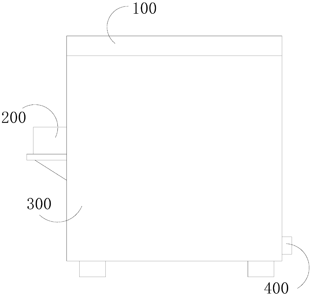
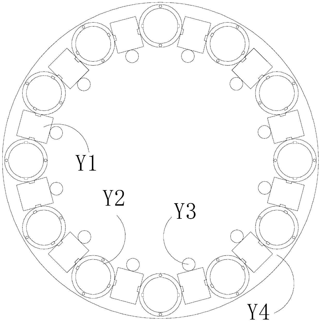
[0031] see Figure 1-6 , the present invention provides a technical scheme of a chip pickling device: its structure includes a top cover 100, a chip placement rotating mechanism 200, a pickling machine body 300, and a pickling liquid discharge pipe 400, and the top of the pickling machine body 300 is hinged to There is a top cover 100, the pickling machine body 300 is provided with a chip placement rotating mechanism 200, and the bottom of one side of the pickling body 300 is connected with a pickling solution discharge pipe 400, and the chip placement rotating mechanism 200 is set to be able to Place the chips to be pickled so that the chips are placed independently one by one to avoid area overlap when the chips are stacked, which helps to improve the efficiency and effect of pickling.

[0032] The chip placing and rotating mechanism 200 is coated with a strong oxidation-resistant coating, which can prevent corrosion by pickling solution and help to improve the service life ...

Embodiment 2

[0038] see Figure 1-12 , the present invention provides a technical scheme of a chip pickling device: its structure includes a top cover 100, a chip placement rotating mechanism 200, a pickling machine body 300, and a pickling liquid discharge pipe 400, and the top of the pickling machine body 300 is hinged to There is a top cover 100, the pickling machine body 300 is provided with a chip placement rotating mechanism 200, and the bottom of one side of the pickling body 300 is connected with a pickling solution discharge pipe 400, and the chip placement rotating mechanism 200 is set to be able to Place the chips to be pickled so that the chips are placed independently one by one, avoiding area overlap when chips are stacked, and helping to improve the efficiency and effect of pickling.

[0039] The chip placing and rotating mechanism 200 is coated with a strong oxidation-resistant coating, which can prevent corrosion by pickling solution and help to improve the service life of...


PUM


Abstract

The invention discloses a chip pickling device. The device structurally comprises a top cover, a chip placing and rotating mechanism, a pickling machine body and a pickling solution discharge pipe. The top cover is hinged to the top of the pickling machine body; the pickling machine body is provided with the chip placing and rotating mechanism; and the bottom of one side of the pickling machine body is communicated with the pickling solution discharge pipe. Compared with the prior art, the device has the beneficial effects that: chips to be pickled can be placed, and the chips are independently placed one by one, so that area overlapping caused by chip stacking can be avoided, the contact area of the chips and the pickling solution is increased, and the acid washing efficiency and effect can be improved; in the pickling process, the chips can rotate with the rotating shaft as the axis, so that the chips and pickling water generate counterforce, so that pickling of the chips by the pickling water is more facilitated, and pickling of the chips is more sufficient; and after cleaning, stretching of the springs facilitates loosening of the pickled chips by the supporting blocks and pouring out of all the chips, and taking of the chips one by one is not needed.

Description

technical field [0001] The invention relates to the technical field of semiconductors, in particular to a chip pickling device. Background technique [0002] A diode is an electronic device made of semiconductor materials. It has unidirectional conductivity, that is, when a forward voltage is applied to the anode and cathode of the diode, the diode conducts. In the production process of the diode, the chip needs to be For pickling, the current pickling method for chips is to place the chip to be pickled directly in the pickling pool, and the chip is also placed flat, and the contact area between the chip and the pickling solution is easily caused by the overlapping of the chip area. Small, so that the pickling efficiency of the chip is low, the pickling effect is poor, and the pickling of the chip is not thorough enough. Contents of the invention [0003] The main purpose of the present invention is to overcome the deficiencies of the prior art and provide a chip pickling...

Claims


Application Information

Patent Timeline
Patent Type & Authority Applications(China)
IPC IPC(8): H01L21/67H01L21/687
CPCH01L21/6704H01L21/68721H01L21/68764H01L21/68785
Inventor 郭志锋
Owner 郭志锋
Why Eureka
Try Eureka