Tripping circuit and method, control circuit and electric leakage detection system thereof
A tripping circuit and control circuit technology, applied in the electronic field, can solve problems such as high cost, equipment blown up, strong Miller effect, etc.
- Summary
- Abstract
- Description
- Claims
- Application Information
AI Technical Summary
Problems solved by technology
Method used
Image

Examples
Embodiment 1
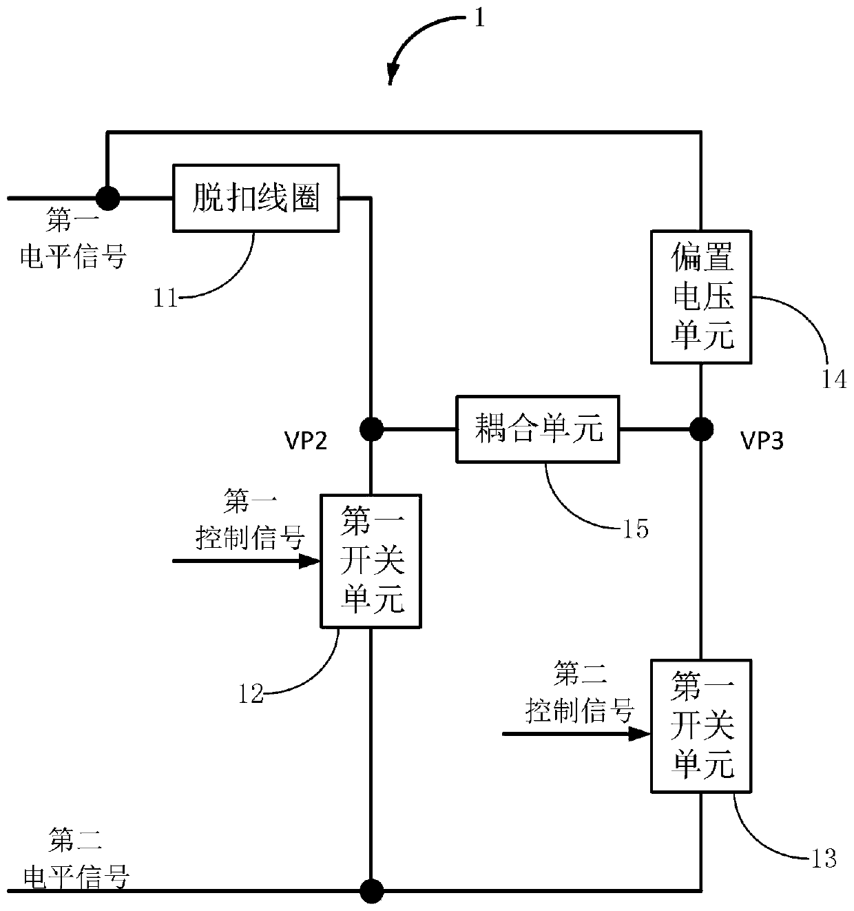
[0168] Such as figure 2 As shown in the control timing diagram of the tripping circuit of the present invention: the upper part is the waveform of the first control signal; the lower part is the waveform of the second control signal. The waveform can be square wave, sine wave, triangular wave and other waveforms for driving thyristor and MOS, here only square wave is used as an example.
[0169] P1, P2...PN are the first cycle, the second cycle...the Nth cycle.
[0170] T1, T2, T3, T4, and T5 are different times.
[0171] It can be seen from the figure:
[0172] At time T1, the first control signal outputs a high level (first control level), and at this time the first switch unit is triggered;
[0173] At time T2, the first control signal outputs a low level (second control level), and at this moment, the first switch unit stops triggering;
[0174] At time T3, the second control signal outputs a high level (third control level), and at this time the second switch unit is...
Embodiment 2
[0206] Application in medium voltage AC mode:
[0207] Such as Figure 6 Shown in the leakage detection system under the medium voltage alternating current mode of the tripping circuit of the present invention, and Figure 5 The difference is that the first level voltage signal is generated by the medium voltage alternating current through the rectification unit 22; the second level voltage signal is a ground (GND) signal.
Embodiment 3
[0209] Application in high voltage AC mode:
[0210] Such as Figure 7 The leakage detection system of the tripping circuit of the present invention under AC high voltage mode; as shown in the figure, the AC voltage is high voltage, which can reach 380V and above.
[0211] and Figure 6 The difference is that the first level voltage signal is generated by high-voltage alternating current through the rectification unit; the second level voltage signal is a ground signal.
[0212] and Figure 6 Another difference is that, in order to make the first switch unit SCR Q2 can withstand a good voltage (the voltage of the first level signal generated by the rectifier unit 22 after passing through the tripping coil, that is, the aforementioned third voltage signal), A voltage dividing module 23 is added, and the voltage dividing module 23 is mainly implemented by connecting the thyristor Q3 in series between the third voltage signal and the first switching unit thyristor Q2. Of cour...
PUM
 Abstract
Description
Claims
Application Information
 - R&D
- Intellectual Property
- Life Sciences
- Materials
- Tech Scout
- Unparalleled Data Quality
- Higher Quality Content
- 60% Fewer Hallucinations
Browse by: Latest US Patents, China's latest patents, Technical Efficacy Thesaurus, Application Domain, Technology Topic, Popular Technical Reports.
© 2025 PatSnap. All rights reserved.Legal|Privacy policy|Modern Slavery Act Transparency Statement|Sitemap|About US| Contact US: help@patsnap.com