
Dental implant

A technology of dental implants and body, applied in dentistry, dental implants, dental restorations, etc., can solve problems such as insufficient depth of bone ingrowth, failure to ensure stability, and loosening of implants, so as to achieve stable retention, The effect of ensuring correct installation and reducing the loosening rate

Inactive Publication Date: 2020-08-28
河北春立航诺新材料科技有限公司
View PDF9 Cites 1 Cited by
  • Summary
  • Abstract
  • Description
  • Claims
  • Application Information

AI Technical Summary

Problems solved by technology

However, a layer of tantalum coating is attached to the bottom surface of the implant, and the depth of bone growth in the later stage is insufficient to ensure the stability in the later stage, and implant loosening is prone to occur in the elderly

Method used


Image

  • Dental implant
  • Dental implant

Examples


Embodiment 1

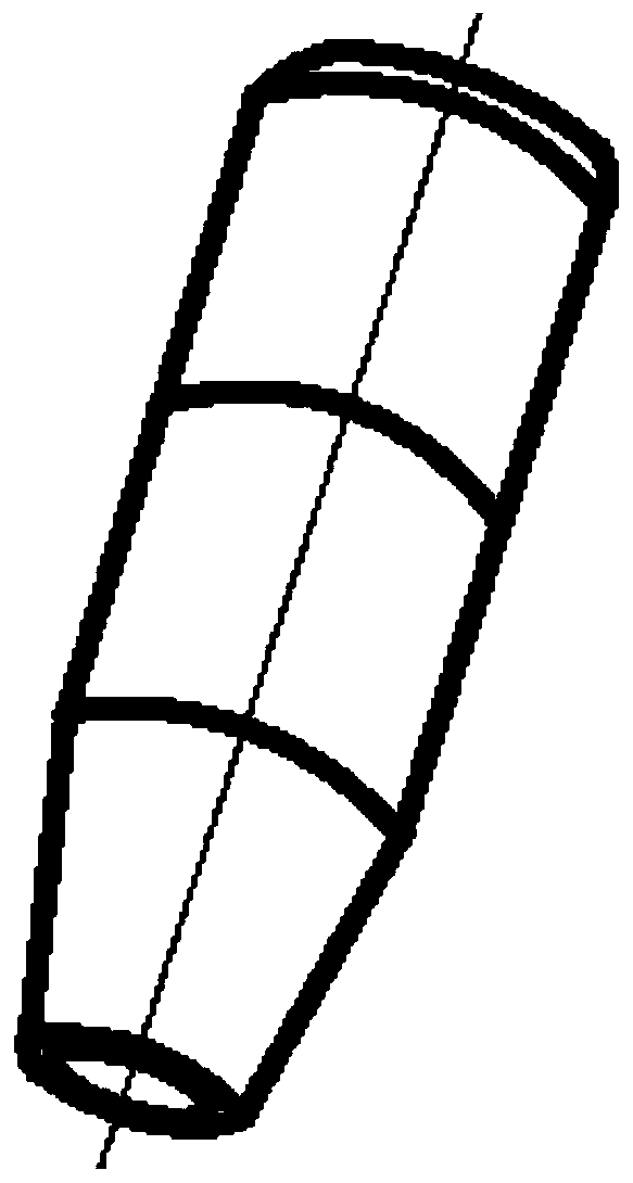
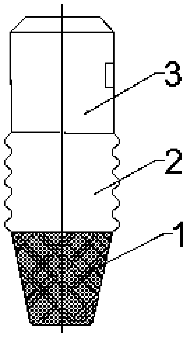
[0027] Please refer to the attached Figure 1-2 , the purpose of this embodiment is to provide a dental implant, a dental implant comprising: a dental implant body, the dental implant body has a root 1 , a bottom 2 and an end 3 .

[0028] Specifically, the root 1 has a conical structure, which can better match the structural features of the alveolar bone. The material of the root 1 of the dental implant body is tantalum metal, and the outer surface of the root 1 is provided with a bone trabecular structure. The porosity of the bone trabecular structure is 75%. The wire diameter of the structure is 400 μm, and the pore size of the trabecular bone structure is 600 μm. The trabecular bone structure can improve the biocompatibility of dental implants, optimize the overall performance of dental implants, increase the contact area with normal bone through the pores on the surface of trabecular bone, provide space for bone ingrowth, and speed up clinical The speed of osseointegrati...

Embodiment 2

[0032] Please refer to the attached Figure 1-2 , the purpose of this embodiment is to provide a dental implant, a dental implant comprising: a dental implant body, the dental implant body has a root 1 , a bottom 2 and an end 3 .

[0033] Specifically, the root 1 has a conical structure, which can better match the structural features of the alveolar bone. The material of the root 1 of the dental implant body is tantalum metal, and the outer surface of the root 1 is provided with a bone trabecular structure. The porosity of the bone trabecular structure is 85%. The wire diameter of the beam structure is 400 μm, and the pore size of the trabecular bone structure is 600 μm. The trabecular bone structure can improve the biocompatibility of dental implants, optimize the overall performance of dental implants, increase the contact area with normal bone through the pores on the surface of trabecular bone, provide space for bone ingrowth, and speed up clinical The speed of osseointe...


PUM

PropertyMeasurementUnit
Wire diameteraaaaaaaaaa
Apertureaaaaaaaaaa

Abstract

The invention relates to the technical field of medical instruments, and provides a dental implant. The dental implant comprises a dental implant body, and the dental implant body is provided with a root dental implant, a bottom dental implant and an end dental implant; the root dental implant is of a conical structure, the outer surface of the root dental implant is provided with a bone trabeculastructure, the bottom dental implant and the end dental implant are of cylindrical structures, the outer surface of the bottom dental implant is provided with an external thread, the outer surface ofthe end dental implant is provided with a plurality of anti-rotation grooves, and the anti-rotation grooves are arranged at intervals of 90 degrees. The dental implant has the beneficial effects that: the bone trabecula structure can improve the biocompatibility of the dental implant; the external thread structure can improve the tightness between the implant and the bone tissue, increase the contact area between the implant and sclerotin, and realize good cooperation; and the anti-rotation grooves are matched with a base table to prevent the base table from rotating, and correct installationof the base table is guaranteed.

Description

technical field [0001] The invention relates to the technical field of medical instruments, and more specifically, relates to a dental implant. Background technique [0002] Dental implants, as one of the important parts of dental implants, play a role in supporting teeth and achieving the purpose of fixing in the alveolar bone. [0003] Existing dental implants are generally in the shape of a cylinder, and the material is mostly pure titanium or titanium alloy. Threads are provided on the surface of the cylinder to achieve a more stable installation, and the contact surface between the existing dental implant and the alveolar ridge adopts a planar structure, so that the alveolar bone at the alveolar After the alveolar bone is installed, it is necessary to grind the alveolar bone at the alveolar ridge so that the end surface of the alveolar bone at the alveolar ridge is flush with the top surface of the dental implant. In this way, grinding the alveolar bone makes the patie...

Claims


Application Information

Patent Timeline
IPC IPC(8): A61C8/00
CPCA61C8/0012A61C8/0025A61C8/0037A61C8/0048A61C2008/0046
Inventor 史春生史春宝康树靖王建超李宁许奎雪王建国岳术同
Owner 河北春立航诺新材料科技有限公司
Learn More