Double-sided spot welding system

A double-sided spot welding and spot welding technology, which is applied in the field of parts welding, can solve the problems of difficult gripping by manipulators, high manual labor intensity, high production and maintenance costs, and achieve low operating and maintenance costs, reduced investment costs, and labor costs. low intensity effect

Pending Publication Date: 2020-08-28
天津津岛船务有限公司
View PDF0 Cites 2 Cited by
  • Summary
  • Abstract
  • Description
  • Claims
  • Application Information

AI Technical Summary

Problems solved by technology

Traditional automatic welding equipment usually uses a manipulator to transfer the material to the designated position before welding. However, the material used for welding is often flat, and the manipulator is not easy to pick it up. Therefore, it is usually used for manual loading, which leads to low production efficiency and high labor intensity. and high production cost
However, the clamping device often has a difference between the clamping position and the predetermined position, which will cause a deviation in the mounting position, and the unevenness of the gap will cause the welding pressure to fluctuate, which will cause a significant difference in the strength of each solder joint. Causes severe splashing, resulting in high scrap rates
At the same time, the existing automatic spot welding equipment is generally linear spot welding, while the curved spot welding mostly uses spot welding robots. The former has poor applicability, while the latter often has a complex structure and high production and maintenance costs.

Method used


Image

  • Double-sided spot welding system
  • Double-sided spot welding system
  • Double-sided spot welding system

Examples


Embodiment Construction

[0029] The present invention will be further described in detail below through the specific examples, the following examples are only descriptive, not restrictive, and cannot limit the protection scope of the present invention with this.

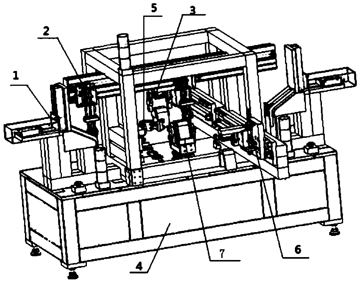
[0030] A double-sided spot welding system, comprising a U-shaped plate feeding conveyor belt, two side plate feeding devices 1, a side plate feeding manipulator 2, a spot welding main machine, and a blanking manipulator 3. The spot welding main machine is fixed On an operating cabinet 4, the left and right sides of the spot welding main frame are symmetrically fixed on both sides of the plate feeding device, and the side plate feeding manipulator is fixed on the spot welding main frame between the two sides of the plate feeding device. The place ahead of spot-welding main frame installs U-shaped plate feeding conveyor belt, installs U-shaped plate feeding manipulator 6 above the end section of U-shaped plate feeding conveying belt, and instal...


PUM


Abstract

The invention relates to a double-sided spot welding system which comprises a U-shaped plate feeding conveying belt, two side plate feeding devices, a side plate feeding mechanical arm, a spot weldingmain machine and a discharging mechanical arm. The spot welding main machine is fixedly installed on an operation cabinet, and the two side plate feeding devices are symmetrically and fixedly installed on the left side and the right side of the spot welding main machine, the side plate feeding mechanical arm is fixedly installed above the spot welding main machine and between the two side plate feeding devices through a support, a U-shaped plate feeding conveying belt is installed in front of the spot welding main machine, a U-shaped plate feeding mechanical arm is installed above a tail section of the U-shaped plate feeding conveying belt, and a finished product discharging mechanical arm is installed behind the spot welding main machine; and the spot welding main machine comprises a spot welding clamping rotating device and a spot welding gun swinging device. According to the double-sided spot welding system, programmable automatic feeding of a control cabinet is adopted, double-face spot welding of one welding gun can be achieved, the manual labor intensity is low, and the production efficiency is high.

Description

technical field [0001] The invention belongs to the field of component welding, and relates to welding equipment, in particular to a double-sided spot welding system. Background technique [0002] In recent years, with the development of digitization, automation, computer and mechanical design technology, and the high emphasis on welding quality, automatic welding has developed into an advanced manufacturing technology, and the role played by automatic welding equipment in the application of various industries Increasingly, the scope of application is rapidly expanding. In modern industrial production, the mechanization and automation of the welding production process is an inevitable trend in the modernization of the welding mechanism manufacturing industry. [0003] When the automatic welding equipment is working, it usually uses a manipulator to transfer the material to be welded to the designated position and then clamps and limits it, so that the weldment is fixed to t...

Claims


Application Information

Patent Timeline
Patent Type & Authority Applications(China)
IPC IPC(8): B23K37/00B23K37/02B23K37/047
CPCB23K37/00B23K37/0211B23K37/047
Inventor 王嵩
Owner 天津津岛船务有限公司
Why Eureka
Try Eureka