
Anti-skid device for climbing-free device for wind turbine generator and design method thereof

A technology for wind turbines and anti-skid devices, applied in hoisting devices, safety devices for lifting equipment, etc., can solve problems such as accelerated drive wheels, driven wheel bearing wear, reduced equipment service life, and easily damaged wire ropes, etc., to increase contact length, Ensure reliable operation and improve the effect of anti-skid ability

Pending Publication Date: 2020-08-28
GUODIAN UNITED POWER TECH
View PDF0 Cites 0 Cited by
  • Summary
  • Abstract
  • Description
  • Claims
  • Application Information

AI Technical Summary

Problems solved by technology

Due to the short contact length between the drive wheel and the wire rope, and the limited positive pressure p applied by the anti-skid device, when the friction coefficient μ decreases a lot, if the weight of the transported object is close to the rated maximum transport capacity of the free-climbing device, slipping will still occur
[0007] In addition, the existing design simply adopts the spring preload method as the limited ability to apply the positive pressure p. If the preload is too large, it is easy to damage the steel wire rope, accelerate the wear of the bearings of the driving wheel and the driven wheel, reduce the service life of the entire equipment, and cause new problems. Potential hidden danger
[0008] This shows that the above-mentioned existing anti-climbing device anti-skid device obviously still has inconvenience and defects in structure, method and use, and needs to be further improved urgently

Method used


Image

  • Anti-skid device for climbing-free device for wind turbine generator and design method thereof
  • Anti-skid device for climbing-free device for wind turbine generator and design method thereof
  • Anti-skid device for climbing-free device for wind turbine generator and design method thereof

Examples


Embodiment Construction

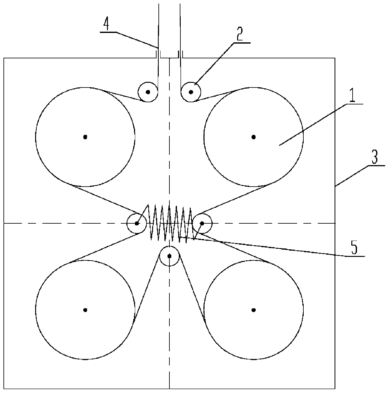
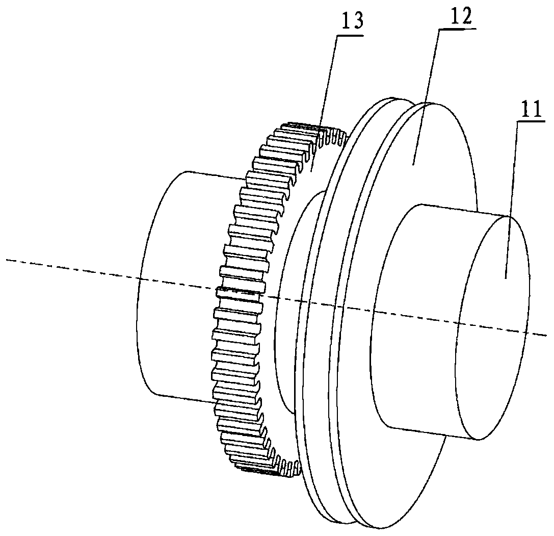
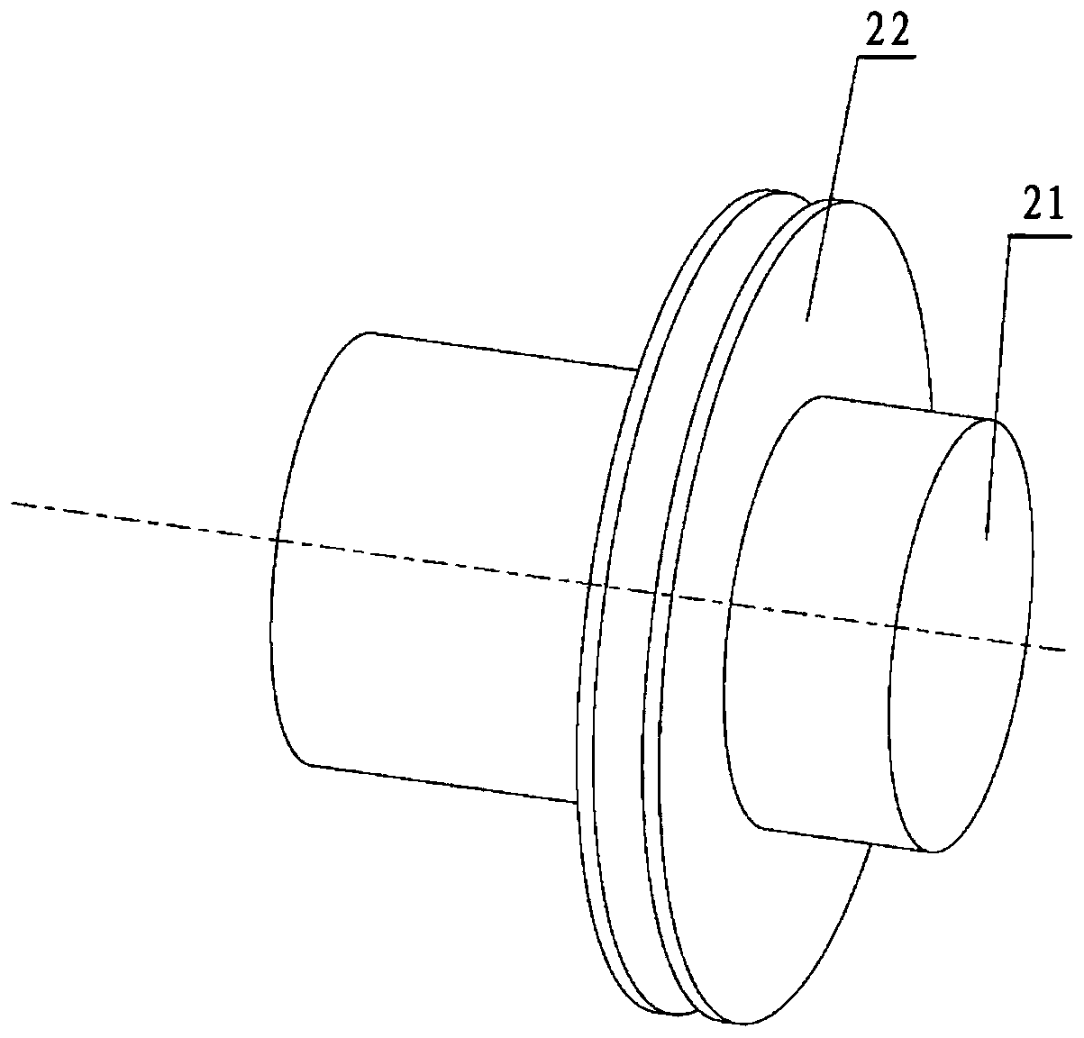
[0037] see figure 1 , the present invention provides an anti-skid device for a wind turbine free climber, including a power box 3, a driving wheel 1, a driven wheel 2, a steel wire rope 4 and a preload spring 5, and the driving wheel 1 and the driven wheel 2 are installed in the power box 3 , one end of the steel wire rope 4 passes through the power box 3 and then goes around the driving wheels 1 and driven wheels 2 and then passes out from the power box 3. In this embodiment, the wire rope 4 penetrates into and out of the power box 3 The inlet and outlet are all located above the power box 3, the number of the driving wheels 1 is four, and the number of the driven wheels is five, the driving wheels 1 are arranged in an equidistant rectangle, and the driven wheels 2 are wound on the wire rope The direction of the driving wheel 1 is arranged at intervals, specifically, two of the five driven wheels 2 are arranged on the horizontal center line of the rectangle formed by the driv...


PUM


Abstract

The invention discloses an anti-skid device for a climbing-free device for a wind turbine generator and a design method thereof. The anti-skid device for the climbing-free device for the wind turbinegenerator comprises a power box, driving wheels, driven wheels, a steel rope and a pre-tightening spring; the driving wheels and the driven wheels are installed in the power box; at least two drivingwheels are arranged; the steel rope passes through the power box and sequentially bypasses the driving wheels and the driven wheels; the power box is internally provided with a guide groove; at leasttwo driven wheels are floating wheels; a wheel shaft of each floating wheel is installed inside the guide groove; and the wheel shafts of the floating wheels are connected through the pre-tightening spring. According to the anti-skid device disclosed by the invention, a plurality of small-diameter driving wheels are used to replace a single large-diameter driving wheel in the existing design; thecontact length between the driving wheels and the steel rope is increased; reliable running of a transmission system is guaranteed; the transmission capability of the driving wheels is also improved;and the skid resistance of the climbing-free device under extremely severe working conditions is improved.

Description

technical field [0001] The invention relates to the field of maintenance equipment for wind turbines, in particular to an anti-skid device for a climb-free device of a wind turbine and a design method thereof. Background technique [0002] With the increase of the power of a single wind turbine unit, the height of the tower is also increased. The standard climbing aids previously equipped with the unit can no longer meet the needs of personnel getting on and off the cabin. More and more complete machine manufacturers will use the climbing aids As a standard configuration for units with a power level of 2MW and above. The current working mode of the unit climbing device is: the motor drives the driving wheel, and the driving wheel transmits the driving force to the steel wire rope through sliding friction. Cooperating with the fixed pulley arranged on the ladder, the steel wire rope drives the part of the manned platform to realize the lifting function. [0003] The existing...

Claims


Application Information

Patent Timeline
Patent Type & Authority Applications(China)
IPC IPC(8): B66F11/04B66F17/00
CPCB66F11/04B66F17/006B66F19/00B66D3/20
Inventor 刘金鹿潘磊汪正军
Owner GUODIAN UNITED POWER TECH
Learn More