Supercharge Your Innovation With Domain-Expert AI Agents!

Gas detection device and method for drilling fluid in riser pipe

A gas detection and riser technology, which is used in measuring devices, surveying, earthwork drilling, etc., can solve the problem of inability to achieve real-time data transmission, poor use effect, and the inability to meet the requirements of low gas intrusion monitoring by Doppler measurement technology, etc. problems, to achieve the effect of ensuring accuracy and reliability, improving accuracy and reliability, and improving security

Active Publication Date: 2020-08-28
CHINA NAT OFFSHORE OIL CORP +1
View PDF8 Cites 1 Cited by
  • Summary
  • Abstract
  • Description
  • Claims
  • Application Information

AI Technical Summary

Problems solved by technology

The above technologies have been successfully applied in their respective fields, but there are still deficiencies in the quantitative monitoring of gas intrusion. For example, the effect of using polydimethylsiloxane as a semipermeable membrane for oil and gas separation under high temperature conditions is poor; The Le measurement technology cannot meet the requirements in low gas transgression monitoring; the real-time data of the bottom hole pressure sensor is limited by the downhole transmission technology, and real-time data transmission cannot be achieved

Method used


Image

  • Gas detection device and method for drilling fluid in riser pipe
  • Gas detection device and method for drilling fluid in riser pipe
  • Gas detection device and method for drilling fluid in riser pipe

Examples


Embodiment 1

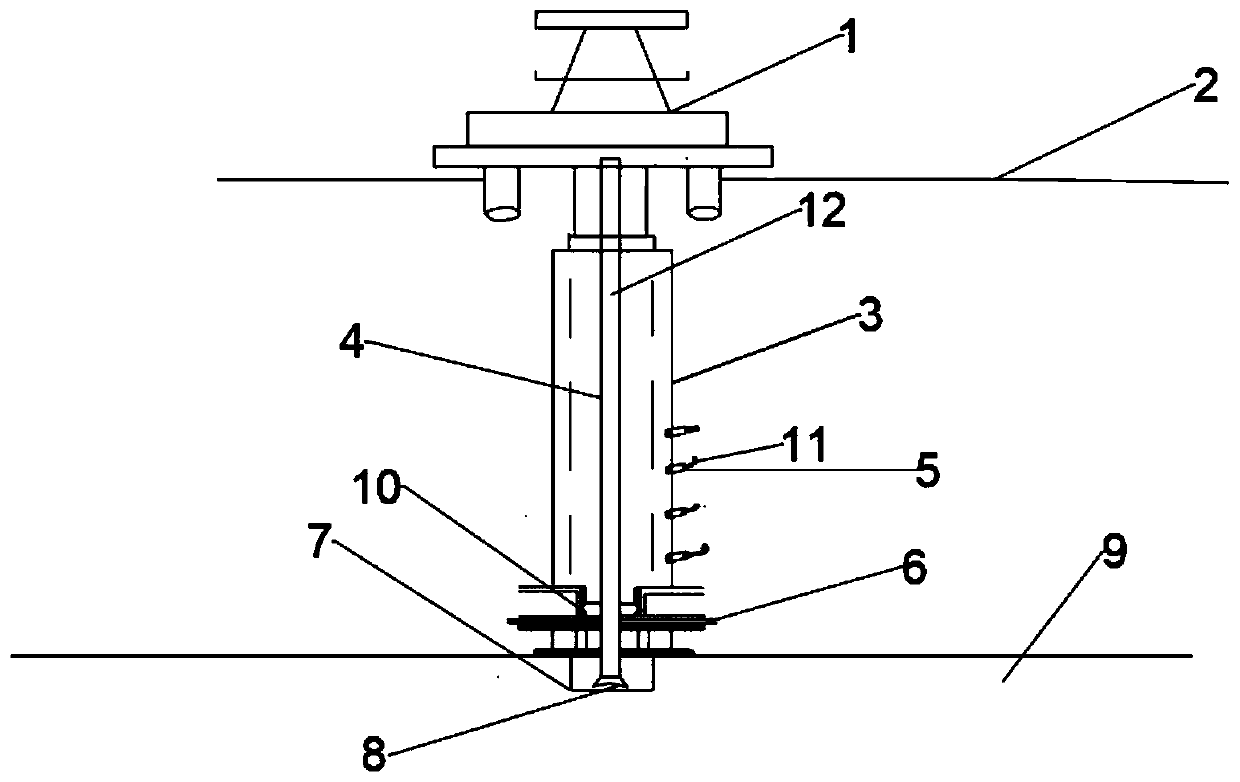
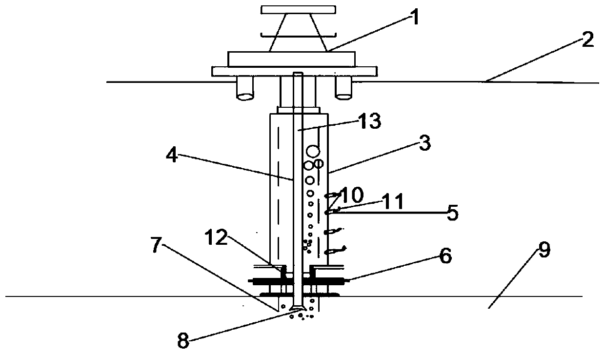
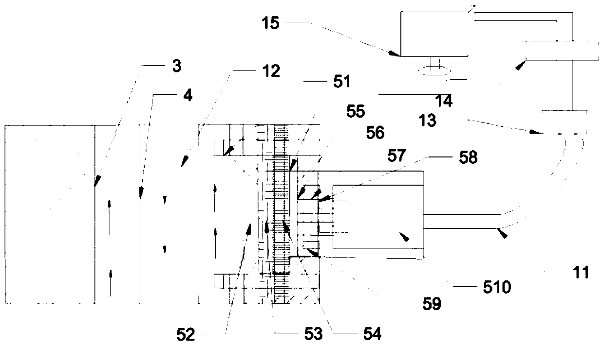
[0028] Such as Figure 1a , 1b , 2, the general layout diagram of the gas detection method device based on the whole semi-permeable membrane, the gas detection device 5 is arranged at a certain distance on the wall surface of the riser 3, the gas detection device 5 is connected with the data transmission cable 11, when the formation 9 overflows When the flowing gas invades, a large amount of gas is dissolved in the drilling fluid 12 in the riser 3, and the gas will be captured when the drilling fluid 12 flows through the gas detection device 5, and transmitted to the front-end signal processor 13 and signal amplifier 14 through the data transmission cable 11, and the signal All have reached a certain amplification, and at the same time, the stability of the transmission signal has been increased. Through the analysis and processing of the platform signal analysis device 15, the degree of air intrusion can be further judged, and corresponding guidance can be made for controlling...

Embodiment 2

[0037] Taking a 4,360-meter-deep well as an example, with a water depth of 1,260 m, the drilling fluid gas detection method in the riser is 41 minutes earlier than the pressure method to monitor the gas entering the riser, and 26 minutes earlier than the surface gas detection method. As shown in the table below:

[0038]


PUM


Abstract

The invention relates to a gas detection device and method for drilling fluid in a riser pipe. The gas detection device comprises a plurality of gas sensing devices, a front-end processor, a signal amplifier and a signal analysis device, a plurality of through holes are formed in the side wall of the riser pipe, and the gas sensing devices are mounted at the through holes; and gas information collected by the gas sensing devices is transmitted to the signal analysis device through the front-end processor and the signal amplifier, and the signal analysis device receives the gas information transmitted by the signal amplifier and analyzes and processes the gas information. A semi-permeable membrane is placed into the wall of the riser pipe together with a sensor, because the semi-permeable membrane has permselectivity, gas in the riser pipe passes through the semi-permeable membrane and thus captured by the sensor, thus the purpose of detecting the gas of the drilling fluid in the riserpipe is achieved, gas invasion and well kick are found in advance, safety in the well drilling process is improved, and occurrence of complex accidents such as well blowout is avoided.

Description

technical field [0001] The invention belongs to the field of petroleum engineering, and in particular relates to a drilling fluid gas detection device and method in a water riser. Background technique [0002] Offshore drilling is a high-risk and high-investment industry. Any small accident will cause huge property losses. In offshore drilling, blowout accidents occur for a long time. In addition to management reasons, the main reason is the monitoring of gas intrusion Poor, once a blowout occurs, the consequences are difficult to control. During drilling, the normal drilling process is that the drilling fluid is pumped into the bottom of the well through the drill pipe through the mud pump, and then returns to the ground through the annular space. The pressure generated by the static night column pressure and the circulation friction can balance the formation pressure and prevent the formation of gas in the formation. wellbore. After the gas kick occurs, the bottom hole p...

Claims


Application Information

Patent Timeline
IPC IPC(8): E21B47/00E21B21/06G01N33/00
CPCE21B47/00E21B21/067G01N33/0062
Inventor 刘书杰殷志明许亮斌李梦博盛磊祥李昊孙宝江章振杰高永海
Owner CHINA NAT OFFSHORE OIL CORP
Features
  • R&D
  • Intellectual Property
  • Life Sciences
  • Materials
  • Tech Scout
  • Unparalleled Data Quality
  • Higher Quality Content
  • 60% Fewer Hallucinations
Learn More