Device and method for obtaining position of liquid displacement surface in rock fracture

A technology of rock cracks and surface positions, applied in the field of liquid displacement in rock cracks, to achieve the effect of great innovation, reasonable and feasible ideas, and simple experimental equipment

Active Publication Date: 2020-08-28
CHINA THREE GORGES UNIV
View PDF13 Cites 4 Cited by
  • Summary
  • Abstract
  • Description
  • Claims
  • Application Information

AI Technical Summary

Problems solved by technology

[0004] Aiming at the problem that researchers cannot directly observe the change of the liquid position during the displacement process, and cannot conduct image analysis by collecting data, the present invention provides a device and method for obtaining the position of the liquid displacement surface in rock fractures. The method has been innovatively upgraded, which can directly observe the motion loss law of filling materials, which is convenient for researchers to observe the law of displacement operation from the plane and elevation. It has the characteristics of intuitive observation, simple operation, and convenient data collection.

Method used


Image

  • Device and method for obtaining position of liquid displacement surface in rock fracture
  • Device and method for obtaining position of liquid displacement surface in rock fracture
  • Device and method for obtaining position of liquid displacement surface in rock fracture

Examples


Embodiment 1

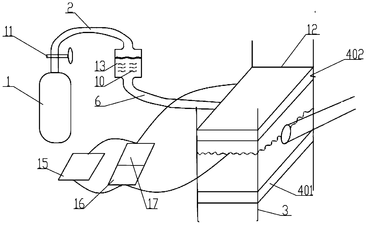
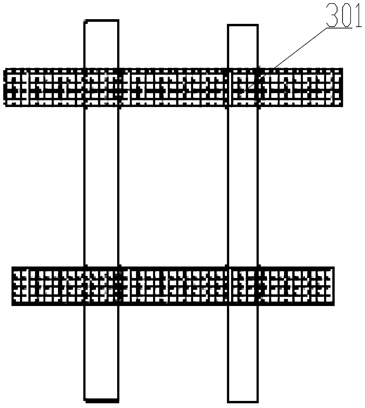
[0051] see Figure 1-7 , a device for obtaining the position of the liquid displacement surface in rock fractures, it includes a water tank 13, the top of the water tank 13 communicates with a gas pressurization device for providing stable pressure; includes a normal stress frame 3, the normal stress Between the frame 3, a rock crack simulation sample 12 for the simulation experiment is installed through a support plate assembly 4, and a plurality of high-speed cameras 8 for monitoring the experimental process are arranged around the rock crack simulation sample 12; The water outlet at the bottom of 13 communicates with the crack connected to the rock crack simulation sample 12 through the high-pressure water pipe 6; the inside of the water tank 13 is filled with tracer bubbles 9 that can change the density and a variety of different densities, incompatible and The solutions 10 with different colors can clearly observe the movement tracks of various incompatible liquids, and t...

Embodiment 2

[0065] The method for performing experiments on the device of the position of the liquid displacement surface in the rock fracture comprises the following steps:

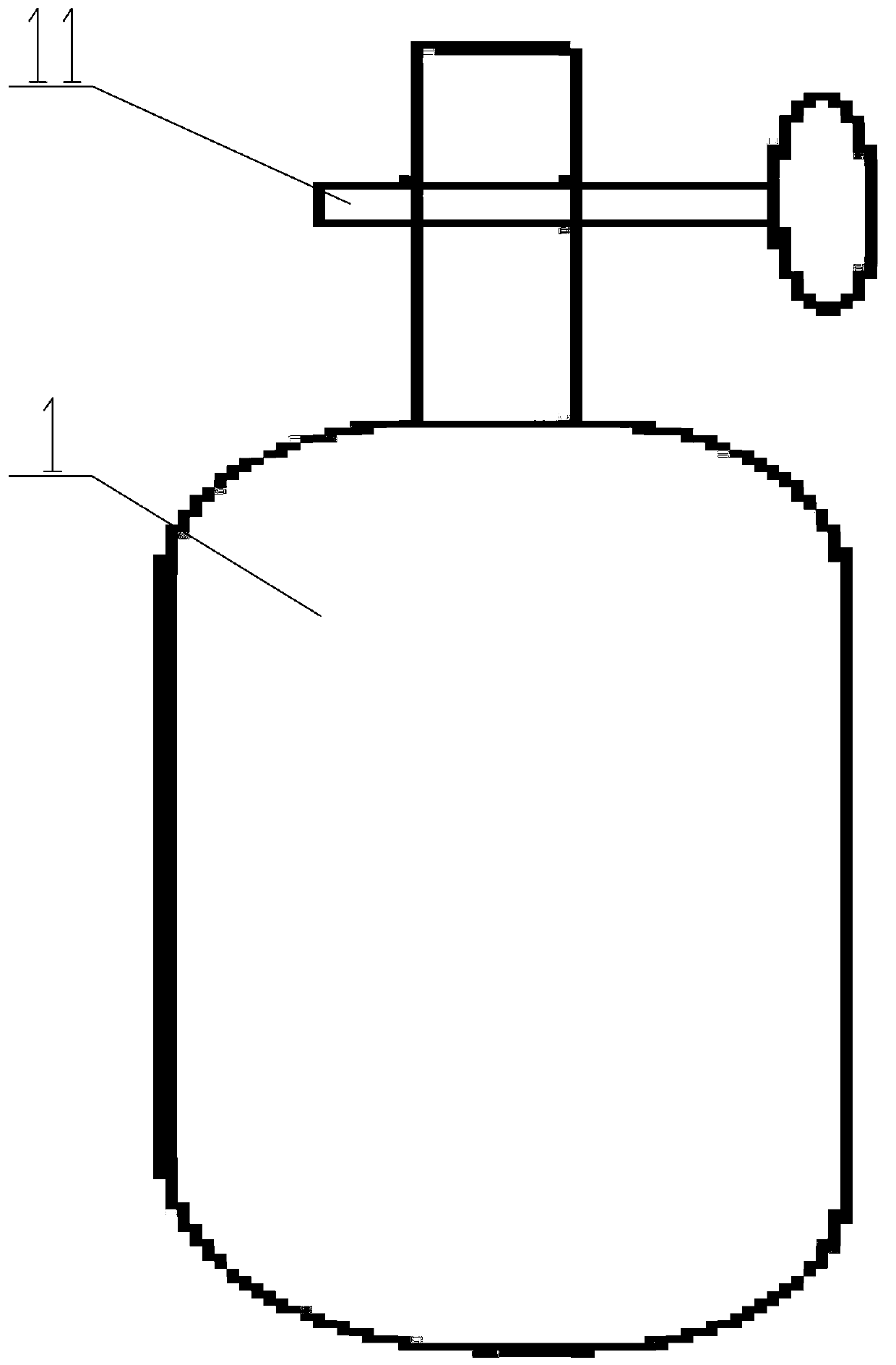
[0066] S1: Provide stable pressure through the gas pressurization device, open the gas control valve 11 of the nitrogen cylinder 1, the compressed nitrogen in the nitrogen cylinder is released, and the released nitrogen enters the water tank 13 through the high-pressure gas pipe 2 to provide air pressure;

[0067] S2: The gas pressure is replaced by the water pressure of the water tank 13, and the gas pressure from the nitrogen cylinder 1 gives pressure to the displacing liquid in the water tank, and pushes the displacing liquid to move toward the outlet of the water tank 13;

[0068] S3: the movement of the displacement fluid in the water tank 13 promotes the movement of the displacement fluid in the experimental area to displace the displaced fluid;

[0069] S4: In the process of injecting the displacement fluid i...


PUM


Abstract

The invention provides a device and method for obtaining the position of a liquid displacement surface in a rock fracture. The top end of a water tank communicates with a gas pressurizing device usedfor providing a stable pressure. The device comprises normal stress frames, a rock crack simulation sample used for a simulation experiment is installed between the normal stress frames through a supporting plate assembly, and a plurality of high-speed cameras used for monitoring the experiment process are arranged on the periphery of the rock crack simulation sample; and a water outlet in the bottom end of a water tank is communicated with a crack communicated with the rock crack simulation sample through a high-pressure water pipe. Therefore, the motion loss rule of the filler can be directly observed, researchers can conveniently observe the displacement operation rule from the plane and the vertical plane, and the device has the advantages of being visual in observation, easy to operate and convenient to collect data.

Description

technical field [0001] The invention relates to the field of liquid displacement in rock fractures, that is, a method for obtaining the position change of the displacement surface at any time by innovating and upgrading the traditional displacement method. Background technique [0002] The displacement process has applications in many aspects of industrial production. If the knowledge and understanding of the displacement process can be improved, the utilization rate of raw materials and production efficiency of industrial production will be improved. For the displacement process, traditional instruments and methods are generally used to study the displacement process in the actual construction process. The advantage is that the production cost is lower and the investment in operating equipment is less. But at the same time, the disadvantage is that usually only the materials at the inlet and outlet (such as outlet pressure, inlet pressure, flow velocity, etc.) can be used ...

Claims


Application Information

Patent Timeline
Patent Type & Authority Applications(China)
IPC IPC(8): G01M10/00G01N13/04G01N15/08G01F23/292
CPCG01M10/00G01N13/04G01N15/08G01F23/292
Inventor 刘杰石谦魏子璇胡青文程怡君王天龙李运舟杨浩宇杜卓兴李政唐洪宇谢晓康李洪亚黎照高素芳孙涛
Owner CHINA THREE GORGES UNIV
Why Eureka
Try Eureka