Capacitor constant-power aging circuit and aging method

A capacitor and constant power technology, which is applied in the field of capacitor constant power sophisticated circuits, can solve problems such as electrolyte evaporation, capacitor withstand voltage rise, electrolytic paper carbonization, etc., to achieve the effects of prolonging service life, improving quality, and preventing evaporation

Pending Publication Date: 2020-08-28
SHENZHEN ZHONGNENGDA AUTOMATION EQUIP CO LTD
View PDF0 Cites 2 Cited by
  • Summary
  • Abstract
  • Description
  • Claims
  • Application Information

AI Technical Summary

Problems solved by technology

[0003] In the traditional capacitor aging process, only a current-limiting resistor is connected in series to charge the capacitor. The aging process of the capacitor usually takes several hours to tens of hours. The surface of the positive electrode foil of the capacitor generates aluminum oxide with insulating properties. With the generation of aluminum oxide, the surface of the positive electrode foil begins to insulate, and the withstand voltage of the capacitor gradually increases.
Since the voltage applied to the capacitor and the resistor during the burn-in process is higher than the withstand voltage of the capacitor's aluminum foil, even if there is a current-limiting resistor connected in series, as the voltage increases slowly, the current flowing through the capacitor can generate very high heat , leading to the evaporation of the electrolyte inside the capacitor, and carbonization of the electrolytic paper, which seriously affects the service life of the capacitor

Method used


Image

  • Capacitor constant-power aging circuit and aging method
  • Capacitor constant-power aging circuit and aging method
  • Capacitor constant-power aging circuit and aging method

Examples


Embodiment Construction

[0029] The present invention will be further described below in conjunction with the embodiments and accompanying drawings. It should be noted that the following description is only to help readers better understand this patent, so it only describes one or several specific implementations. The protection of this patent The scope is not limited to the following specific embodiments, but should include various changes made by those skilled in the art using conventional technical means.

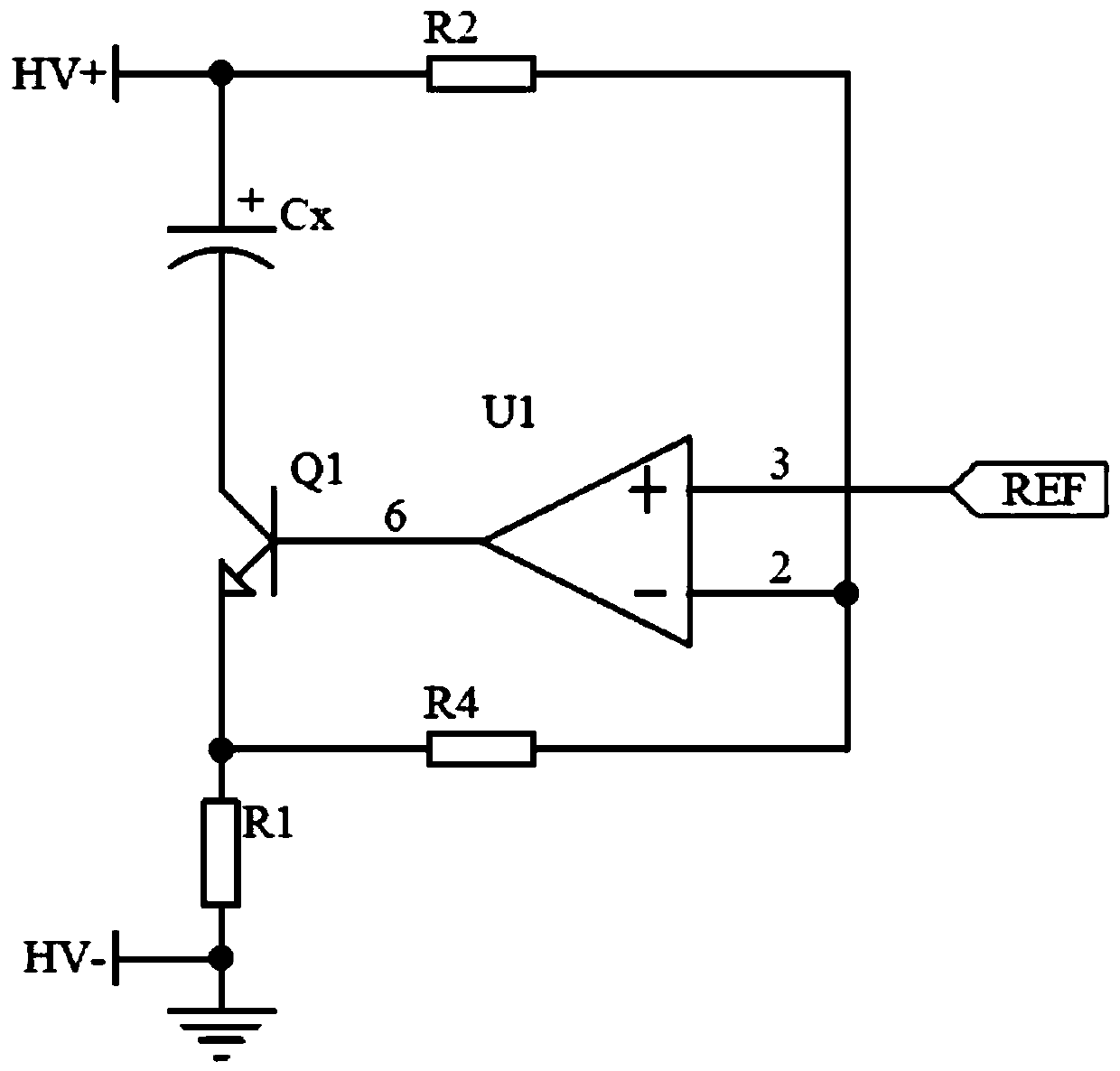
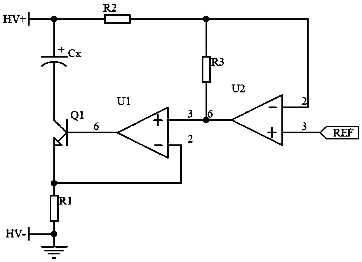
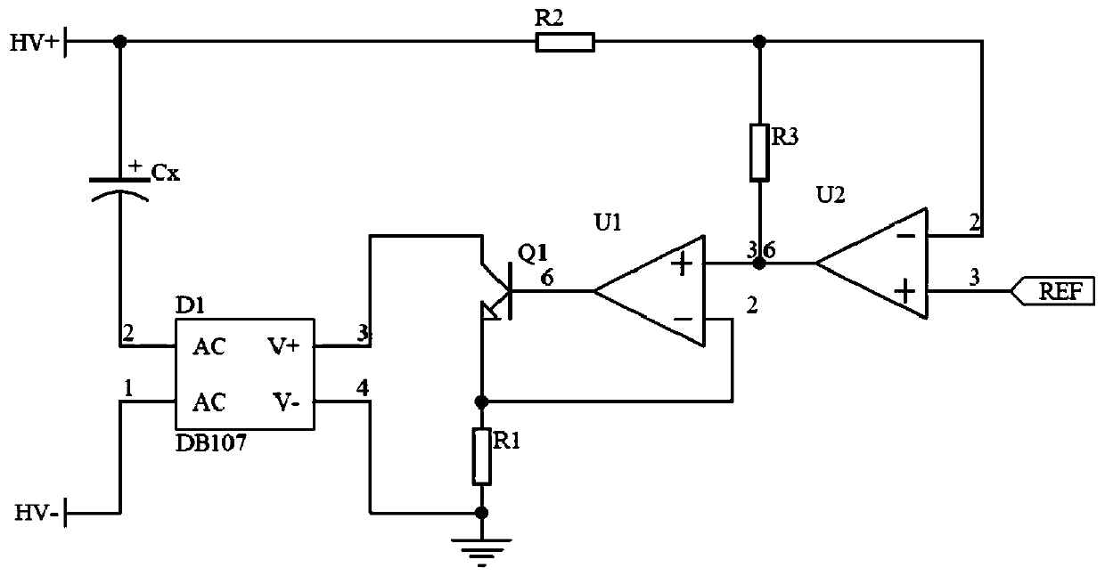
[0030] The invention provides a capacitor constant power aging circuit, which is used for the aluminum electrolytic capacitor constant power aging device, including the output terminal of the charging power supply, the capacitor Cx to be aged, the transistor Q1, and the operational amplifier U1, in addition to the forward input of the operational amplifier The terminal is connected with a reference voltage REF; the output terminal of the charging power supply forms a charging circuit with the cap...


PUM


Abstract

The invention provides a capacitor constant-power aging circuit and an aging method thereof, which are used for an aluminum electrolytic capacitor constant-power aging device. The circuit comprise a charging power supply output end, a capacitor Cx to be aged, a transistor Q1 and an operational amplifier U1, in addition, a reference voltage REF is also connected to the positive input end of the operational amplifier; the output end of the charging power supply, the capacitor Cx, the transistor Q1 and the resistor R1 form a charging loop, and the resistor R1 is grounded; meanwhile, the input endof the operational amplifier U1 is connected with a feedback circuit and a reverse adder to form a constant current source. The charging current of the capacitor to be aged is dynamically adjusted according to the voltage loaded on the capacitor, so that the charging current is relatively large when the voltage is low, the charging current is automatically reduced along with the rise of the voltage, the heating value of the capacitor during aging is controlled, and electrolyte evaporation caused by over-high temperature is prevented. The quality of the capacitor can be greatly improved, and the service life of the capacitor is prolonged.

Description

technical field [0001] The invention relates to the technical field of capacitor manufacturing, in particular to a capacitor constant power aging circuit and an aging method thereof. Background technique [0002] Because the formed foil of the capacitor needs to be cut during production, which will destroy the formed aluminum oxide on the surface and lose the original withstand voltage. Therefore, the capacitor needs to be charged to repair the aluminum oxide on the surface of the aluminum foil after the assembly is completed. , this process is commonly known as sophistication. [0003] In the traditional capacitor aging process, only a current-limiting resistor is connected in series to charge the capacitor. The aging process of the capacitor usually takes several hours to dozens of hours. Unaged capacitors cannot be charged, and an electrochemical reaction is required during the charging process. Aluminum oxide with insulating properties is formed on the surface of the po...

Claims


Application Information

Patent Timeline
Patent Type & Authority Applications(China)
IPC IPC(8): H01G9/00H01G9/045H01G13/00H02J7/00H02J7/10
CPCH01G9/0029H01G9/045H01G13/00H02J7/00712H02J7/06
Inventor 廖文昌唐元安
Owner SHENZHEN ZHONGNENGDA AUTOMATION EQUIP CO LTD
Why Eureka
Try Eureka