Compact low cross polarization microstrip antenna

Active Publication Date: 2020-08-28
SHANGHAI JIAO TONG UNIV
View PDF5 Cites 1 Cited by
  • Summary
  • Abstract
  • Description
  • Claims
  • Application Information

AI Technical Summary

Problems solved by technology

However, it cannot effectively improve the cross-polarization problem of traditional short-circuit microstrip antennas

Method used


Image

  • Compact low cross polarization microstrip antenna
  • Compact low cross polarization microstrip antenna
  • Compact low cross polarization microstrip antenna

Examples


Embodiment 1

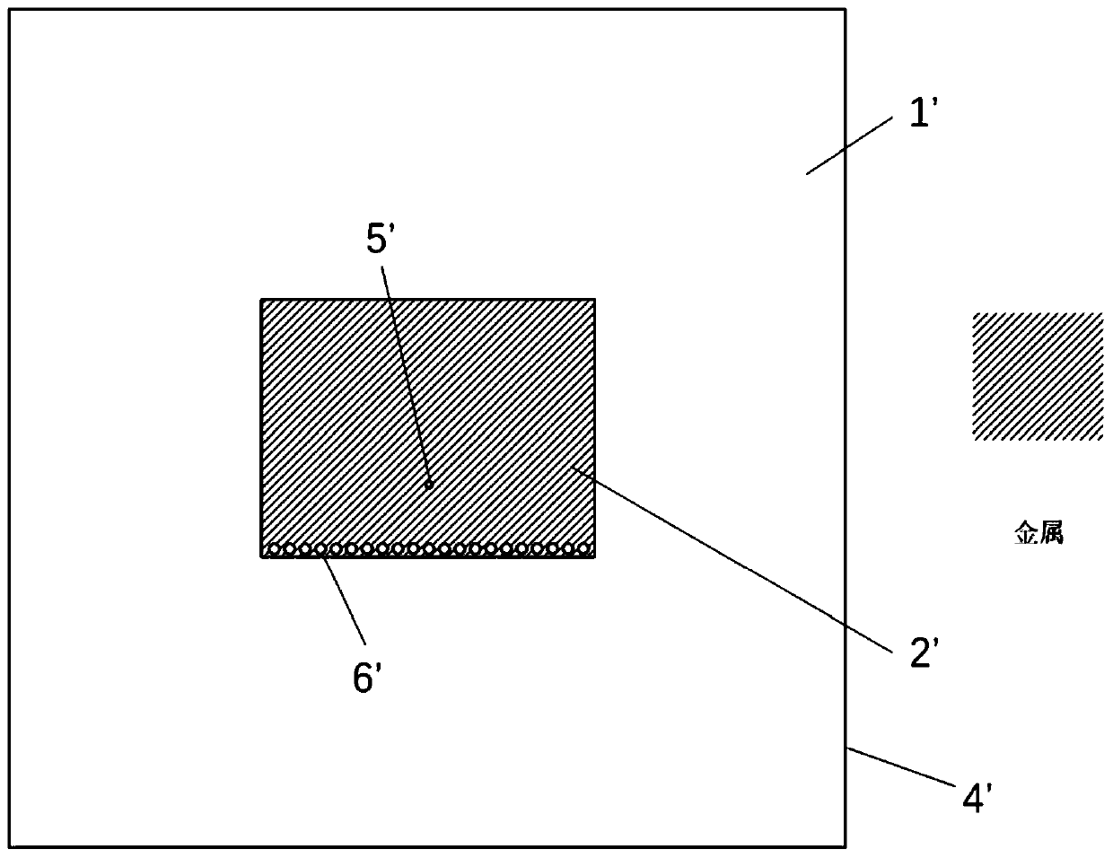
[0040] Such as figure 2 As shown, the traditional microstrip antenna includes a dielectric board 1', a radiation sheet 2', a metal ground 4', a feed interface 5', and a metallized hole 6'. The radiation sheet 2' is set on the upper surface of the dielectric board 1', and the The metal ground 4' is set on the lower surface of the board 1', the outer conductor of the feed interface 5' is connected to the grounding plate, the inner conductor is connected to the radiation sheet 2' on one side, and a row of metallization is arranged along the short side of the radiation sheet 2' Hole 6'.

[0041] The microstrip antenna structure of the present embodiment is as follows:

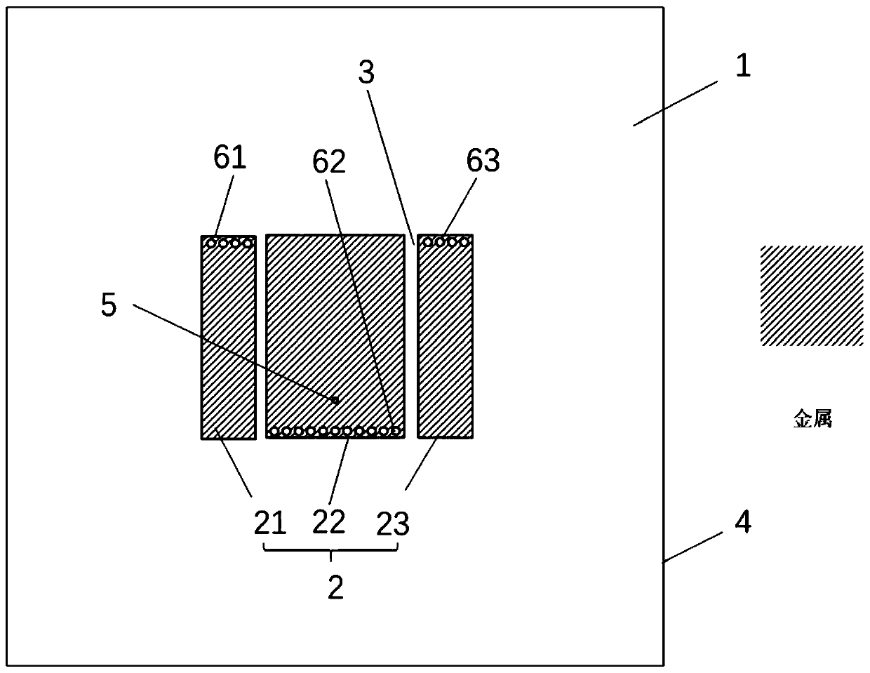
[0042] Such as figure 1 As shown, a compact low cross-polarized microstrip antenna includes a dielectric plate 1, a radiation sheet 2 (the radiation sheet 2 is an axisymmetric pattern), a metal ground 4, a metallized hole 6 and a feed interface 5;

[0043]The radiation sheet 2 and the metal ground 4 are respect...

Embodiment 2

[0051] Embodiment 2 is a modified example of Embodiment 1.

[0052] Such as Figure 8 As shown, in Embodiment 2, the feed interface 5 is arranged on the first radiating sheet 21, and the feeding position is close to the first group of metallized holes 61 on the short-circuit side of the first radiating sheet 21. The rest of the structure is the same as that of Embodiment 1. The feeding distance has no effect on the radiation characteristics of the antenna, but only changes the input resistance. Adjusting the feeding distance can match signal sources with different impedances, usually designed to be 50 ohms.

Embodiment 3

[0054] Embodiment 3 is a modified example of Embodiment 1.

[0055] Such as Figure 9 As shown, in Embodiment 3, two linear gaps 3 with a width of 1mm are provided on the radiation sheet 2, and the two gaps 3 are mirror-symmetrical with respect to the symmetry axis of the second radiation sheet 22, and both are aligned with the second radiation sheet 22. The symmetry axis of 22 has an included angle, and two gaps 3 divide the radiation sheet 2 into the first radiation sheet 21, the second radiation sheet 22 and the third radiation sheet 23; the first radiation sheet 21 and the third radiation sheet 23 are trapezoidal , the second radiation sheet 22 is an inverted isosceles trapezoid; the first radiation sheet 21 and the third radiation sheet 23 are mirror-symmetrical about the symmetry axis of the second radiation sheet 22 . The feeding interface 5 is arranged on the second radiating sheet 22 of inverted isosceles trapezoidal shape, the feeding position is close to the second...


PUM


Abstract

The invention provides a compact low cross polarization microstrip antenna, which comprises a dielectric plate, a radiation sheet, a metal ground, a metallized hole and a feed interface, wherein the metal ground is arranged on the lower surface of the dielectric plate, the radiation sheet is arranged on the upper surface of the dielectric plate, and the metallized hole is formed in the radiation sheet and is connected with the metal ground; an outer conductor of the feed interface is connected with the metal ground, and an inner conductor of the feed interface penetrates through the dielectricplate and is connected to the radiation sheet; the radiation sheet is provided with two gaps, and the two gaps divide the radiation sheet into three parts, namely, a first radiation sheet, a second radiation sheet and a third radiation sheet; and the first radiation sheet and the third radiation sheet are in mirror symmetry about the symmetry axis of the second radiation sheet. According to the invention, the advantages of simple and compact structure are retained, and the cross polarization of the traditional short-circuit microstrip antenna can be greatly improved. Meanwhile, compared withthe traditional short-circuit microstrip antenna, the short-circuit microstrip antenna has a smaller size and is suitable for a radio frequency front-end antenna needing low cross polarization characteristic in a wireless communication system.

Description

technical field [0001] The invention relates to the technical field of antennas, in particular to a compact low-cross-polarization microstrip antenna, which can be used for a radio frequency front end of a wireless communication system. Background technique [0002] Microstrip antenna has been widely researched and applied due to its advantages of low profile, light weight, small size, low cost, easy integration and array formation. The microstrip patch radiates through the two broadsides perpendicular to the surface current, short-circuit the antenna along the center line parallel to the broadside and cut it in half to obtain a short-circuited microstrip antenna. Short-circuit microstrip antennas have been widely used in the design of portable device antennas and miniaturized antennas due to their simple and easy-to-process structures and compact shapes of about 1 / 4 wavelength. Similar to the half-wavelength microstrip antenna, the short-circuit microstrip antenna mainly r...

Claims


Application Information

Patent Timeline
Patent Type & Authority Applications(China)
IPC IPC(8): H01Q1/36H01Q1/38H01Q1/48H01Q1/50H01Q13/08H01Q21/24
CPCH01Q1/36H01Q1/38H01Q1/48H01Q1/50H01Q13/08H01Q21/24
Inventor 邵子剑张跃平
Owner SHANGHAI JIAO TONG UNIV
Why Eureka
Try Eureka