Fourier mode-locked laser device

A technology of mode-locked lasers and optical beam splitters, which is applied in the field of lasers and can solve problems such as poor laser coherence

Active Publication Date: 2020-08-28
THE HONG KONG POLYTECHNIC UNIV SHENZHEN RES INST
View PDF5 Cites 5 Cited by
  • Summary
  • Abstract
  • Description
  • Claims
  • Application Information

AI Technical Summary

Problems solved by technology

[0004] The purpose of the present invention is to provide a Fourier mode-locked laser to solve the technical problem of poor laser coherence produced by existing Fourier mode-locked lasers

Method used


Image

  • Fourier mode-locked laser device
  • Fourier mode-locked laser device
  • Fourier mode-locked laser device

Examples


Embodiment 1

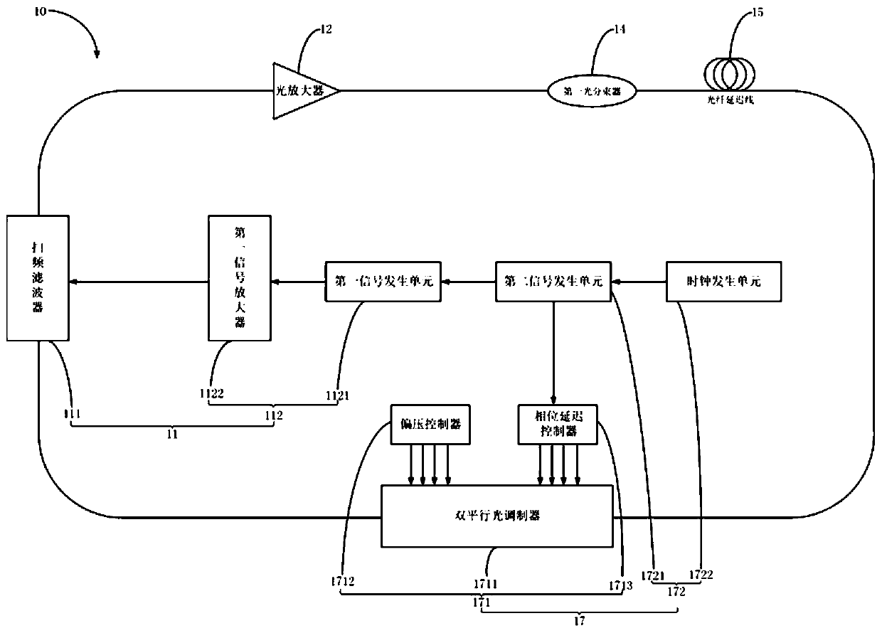
[0091] This embodiment designs a method of using a signal generator to generate RF signals to control the frequency shift of the carrier-suppressed single-sideband modulator, thereby compensating for the frequency shift of the Fourier mode-locked laser 10 due to scattering, nonlinearity, etc., and improving the instantaneous output of the laser. Linewidth (i.e. coherence length). The Fourier mode-locked laser 10 includes a filter module 11, a second optical isolator 18, an optical amplifier 12, a first optical isolator 13, a first optical beam splitter 14, a fiber delay line 15, and a polarization controller arranged in sequence along the circular optical path. 16 and light modulation module 17. The filter module 11 includes a frequency sweep filter 111 and a filter control unit 112, and the frequency sweep filter 111 is connected with the optical amplifier 12; the filter control unit 112 includes a first signal generation unit 1121 and a first signal amplifier 1122, and the f...

Embodiment 2

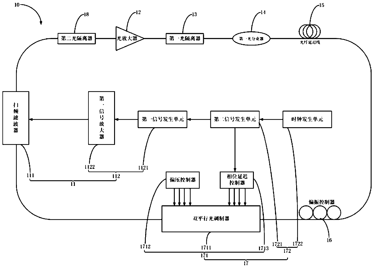
[0094] In this embodiment, a signal generator is used to generate an RF signal to control the frequency shift of the carrier-suppressed single-sideband modulator to compensate the frequency deviation of the discrete Fourier mode-locked laser, and improve the instantaneous linewidth (ie, coherence length) of the laser output. This embodiment is not limited to the continuous frequency-sweeping Fourier mode-locked laser, and is also applicable to the discrete Fourier mode-locked laser. The discrete Fourier mode-locked laser 10 based on frequency shift compensation includes a filter module 11, a second optical isolator 18, an optical amplifier 12, a first optical isolator 13, a first optical beam splitter 14, and an optical fiber arranged in sequence along the ring optical path. Delay line 15 , polarization controller 16 , optical modulation module 17 and multi-channel optical filter 19 . The filter module 11 includes a frequency sweep filter 111 and a filter control unit 112, and...

Embodiment 3

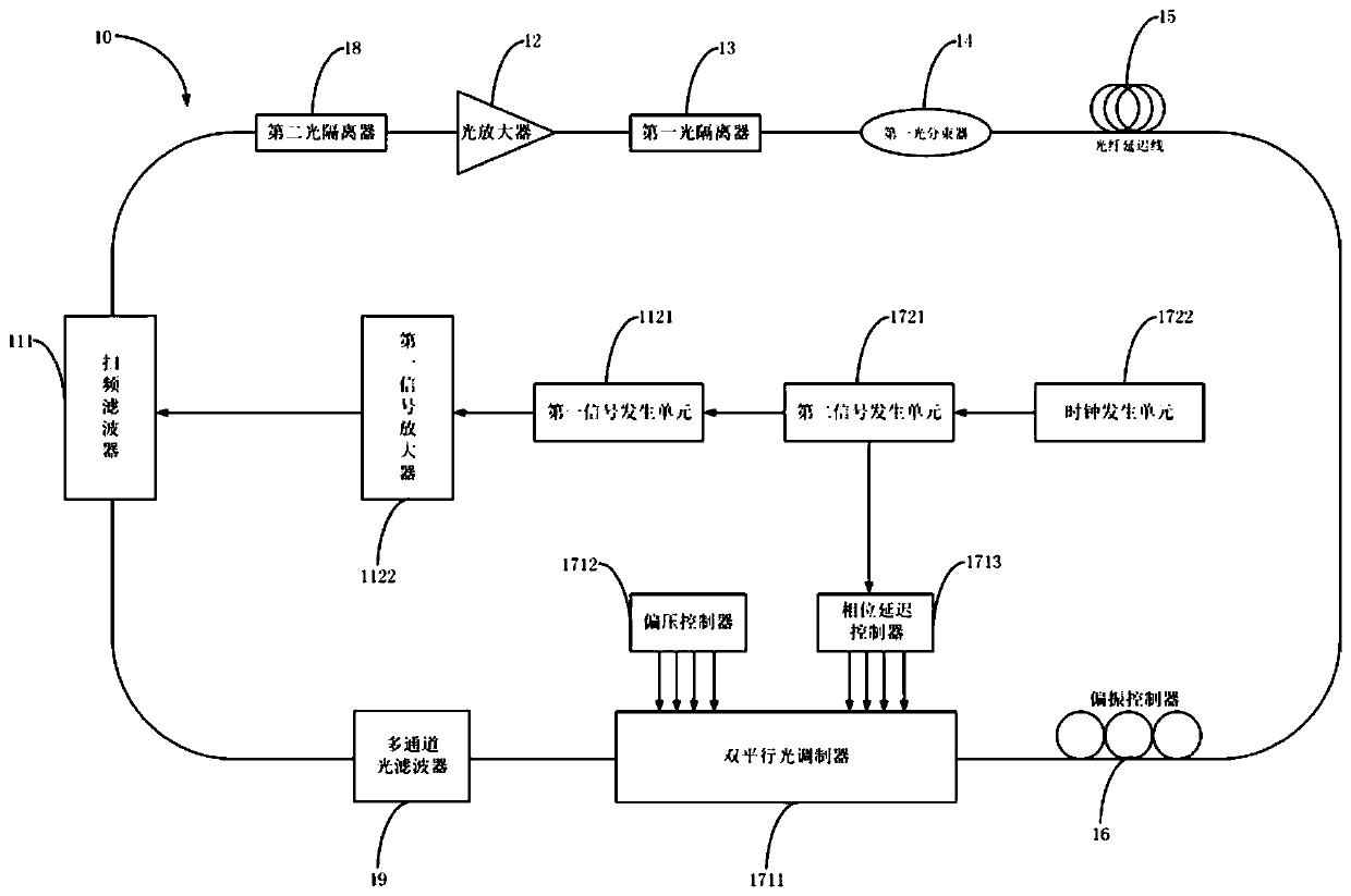
[0097] In this embodiment, a signal generator is used to generate an RF signal to control the frequency shift of the carrier-suppressed single-sideband modulator to compensate the frequency deviation of the discrete Fourier mode-locked laser, and improve the instantaneous linewidth (ie, coherence length) of the laser output. The discretization of the frequency-sweeping signal of the Fourier mode-locked laser 10 in the third embodiment is realized based on the multi-channel optical filter 19. This discretization can also be realized based on the time-domain modulation. The embodiment scheme is designed as image 3 shown.

[0098] The discrete Fourier mode-locked laser 10 based on frequency shift compensation includes a filter module 11, a second optical isolator 18, an optical amplifier 12, a first optical isolator 13, a first optical beam splitter 14, and an optical fiber arranged in sequence along the ring optical path. Delay line 15 , polarization controller 16 , light modul...


PUM


Abstract

The invention relates to the technical field of laser, and provides a Fourier mode-locked laser device, which comprises a filtering module, an optical amplifier, a first optical beam splitter, an optical fiber delay line and an optical modulation module which are arranged along an optical path, wherein the filtering module comprises a sweep frequency filter and a filtering control unit, the filtering control unit is connected with the sweep frequency filter, the optical modulation module comprises an optical modulation unit and a modulation control unit, the modulation control unit is connected with the optical modulation unit, the optical modulation unit is used for carrying out frequency shift compensation on an optical signal, and the modulation control unit is used for controlling thefrequency shift amount of the optical modulation unit. According to the invention, the optical modulation unit is accurately and flexibly controlled through the modulation control unit, so that the optical modulation unit can compensate the frequency offset in the laser cavity, so that the frequency offset in the laser cavity can be effectively eliminated so as to improve the coherence of the laser device.

Description

technical field [0001] The present invention relates to the field of laser technology, and more specifically relates to a Fourier mode-locked laser. Background technique [0002] Fourier mode-locked laser technology is a new type of laser technology in addition to amplitude mode-locking and phase-locking. It is an important technical solution to realize high-speed frequency-sweeping laser light source, because of its high scanning speed, wide scanning range, and narrow instantaneous line width. , has potential applications in optical coherent imaging systems, optical sensing, optical communications, and spectral measurement. [0003] By adding a section of optical fiber in the laser cavity as a delay line, the fundamental frequency of the cavity can be reduced, so that the tuning frequency of the tunable filter can be the same as the fundamental frequency of the cavity, so that each wavelength can cycle through the cavity once and reach the frequency-sweeping filter again ,...

Claims


Application Information

Patent Timeline
Patent Type & Authority Applications(China)
IPC IPC(8): H01S3/10H01S3/11
CPCH01S3/10H01S3/10053H01S3/10061H01S3/1106
Inventor 李锋黄冬梅卫炳江尚超
Owner THE HONG KONG POLYTECHNIC UNIV SHENZHEN RES INST
Why Eureka
Try Eureka