Outer wall cleaning equipment for cleaning building outer wall

A technology for exterior wall cleaning and building exterior walls, applied in cleaning equipment, construction, building maintenance, etc., can solve the problems of high manufacturing and use costs, general cleaning strength, and complex overall structure, and achieve low manufacturing and use costs, The effect of fast cleaning speed and simple overall structure

Inactive Publication Date: 2020-09-01
向朋举
View PDF1 Cites 3 Cited by
  • Summary
  • Abstract
  • Description
  • Claims
  • Application Information

AI Technical Summary

Problems solved by technology

The overall structure of the cleaning equipment is too complicated, resulting in high manufacturing and use costs, and when cleaning the outer wall, the operation is difficult and

Method used


Image

  • Outer wall cleaning equipment for cleaning building outer wall
  • Outer wall cleaning equipment for cleaning building outer wall
  • Outer wall cleaning equipment for cleaning building outer wall

Examples


Embodiment 1

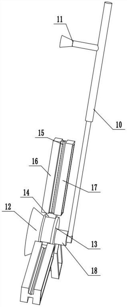
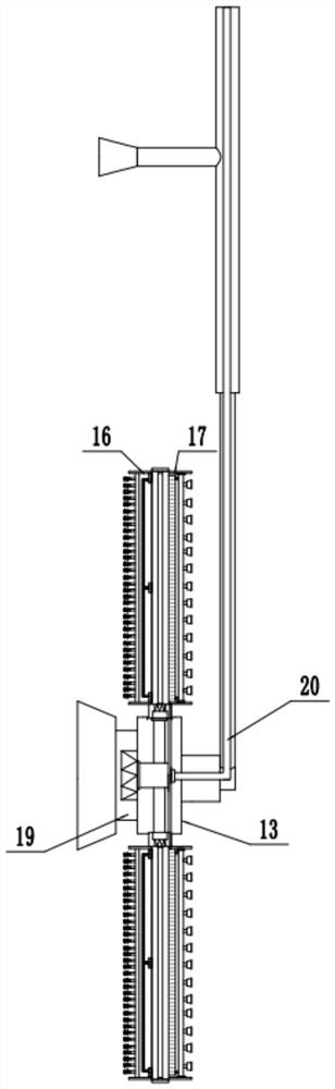
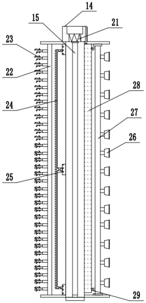
[0023] see Figure 1-4 , an exterior wall cleaning device for cleaning exterior walls of buildings, comprising a lifting rod 10, a mounting base 13, a dust removal tank 16, and a cleaning tank 17; the inside of the mounting base 13 is set as a cavity structure, and the outside A vertical lifting rod 10 is fixedly installed on the side through a connecting rod 18, and the top of the lifting rod 10 is connected upward with a lifting device fixed on the roof, a left and right moving device and a front and rear moving device, and the displacement of the lifting rod 10 is controlled by front, rear, left, right, up and down. , so as to control the position of cleaning the outer wall. A set of main suction cups 12 is fixedly installed on the inner surface of the mounting base 13, and the mounting base 13 can be fixed by adsorbing the main suction cups 12 on the outer wall, thereby facilitating stable cleaning of the outer wall. A set of first servo motors 30 is fixed inside the conn...

Embodiment 2

[0027]On the basis of Embodiment 1, a group of auxiliary suction cups 11 smaller than the main suction cup 12 are fixedly installed on the left side wall of the middle part of the lifting rod 10 to the left. Whether the rod 10 needs to be used or not can be judged by itself based on the stability of the rod 10 in use, and it mainly plays an auxiliary fixing role when the elevating rod 10 and the mounting seat 13 are unstable. The first servo motor 30, the second rotating motor 21, the booster pump 29, and the fan 25 are all electrically connected to the control cabinet fixed on the roof, and the operator controls the operation of each component remotely.

[0028] The working principle of the present invention is: first, according to the position of the outer wall to be cleaned, the installation seat 13 is adjusted to the position to be cleaned by various mobile devices arranged on the roof, and then the opening side of the dust removal tank 16 faces outward wall, so that the b...


PUM


Abstract

The invention relates to the technical field of building outer wall cleaning equipment and discloses outer wall cleaning equipment for cleaning a building outer wall. The equipment comprises a liftingrod, a mounting base, a dust removal tank and a cleaning tank, a set of main suction cups are fixedly mounted on the inner side face of the mounting base, a group of first servo motors are fixed in aconnecting block; the output ends of the right sides of the first servo motors are rotationally connected with rotating shafts extending into the mounting base; three groups of same fixing rods are fixedly mounted on the outer walls of the right sides of the rotating shafts outwards at equal intervals; and a connecting base is fixedly installed at the tail ends of the fixing rods, a second rotating motor is fixed in the connecting base, the output end of the second rotating motor faces the outer side of the connecting base and is rotationally connected with a rotating rod, and a dust removaltank and a cleaning tank are fixedly installed on the left side and the right side of the rotating rod through connecting plates correspondingly. The cleaning equipment has the advantages of simple overall structure, remote operation, high cleaning speed, high strength, high efficiency and low manufacturing and using cost.

Description

technical field [0001] The invention relates to the technical field of equipment for cleaning exterior walls of buildings, in particular to an exterior wall cleaning equipment for cleaning exterior walls of buildings. Background technique [0002] More and more high-rise buildings rise from the ground, followed by the rise of the building exterior wall cleaning industry, and the exterior wall cleaning industry has attracted widespread attention and attention in my country. All the exterior walls of high-rise buildings, due to the sun, wind and rain all year round, as well as the pollution and chemical reactions of harmful gases and oil fumes in the atmosphere, have caused dirt and weathering on the exterior walls of the buildings, which has affected the appearance of the buildings. Peugeot and city appearance, and damaged buildings. [0003] Chinese patent (notification number: CN 110301869 A, announcement date: 2019.10.08) discloses an exterior wall cleaning equipment for ...

Claims


Application Information

Patent Timeline
IPC IPC(8): A47L11/38A47L11/40E04G23/00
CPCA47L11/38A47L11/40A47L11/4036A47L11/4069A47L11/4088E04G23/002
Inventor 向朋举
Owner 向朋举
Why Eureka
Try Eureka