Supercharge Your Innovation With Domain-Expert AI Agents!

Novel liquid collector device

A liquid collector, a new type of technology, applied in chemical instruments and methods, gas treatment, membrane technology, etc., can solve the problems of deviations in the design values ​​of the external dimensions of parts, affecting the normal operation of the desulfurization system, and restricting the quality of production and installation. Achieve the effect of good applicability, good smoke removal effect and simple structure

Pending Publication Date: 2020-09-01
ZHEJIANG TIANDI ENVIRONMENTAL PROTECTION TECH CO LTD
View PDF0 Cites 1 Cited by
  • Summary
  • Abstract
  • Description
  • Claims
  • Application Information

AI Technical Summary

Problems solved by technology

[0004] The gas cap and liquid collection plate in the conventional ammonia desulfurization tower are made of FRP material, and the on-site pasting workload is large. The quality of its production and installation is subject to the construction environment and the hand lay-up level of the construction personnel. The external dimensions of the parts are often different from the design values. There is a deviation
Especially in the northern region, the flue gas in the desulfurization tower has a large temperature difference between the start and stop of the boiler, and due to the difference in thermal expansion coefficient between different materials, the expansion and contraction of the FRP material is likely to cause cracks on the lap joints, resulting in internal leakage of the spray slurry, which seriously affects the Normal operation of the desulfurization system

Method used


Image

  • Novel liquid collector device
  • Novel liquid collector device
  • Novel liquid collector device

Examples


Embodiment Construction

[0033] The present invention will be further described below in conjunction with the examples. The description of the following examples is provided only to aid the understanding of the present invention. It should be pointed out that for those skilled in the art, without departing from the principle of the present invention, some improvements and modifications can be made to the present invention, and these improvements and modifications also fall within the protection scope of the claims of the present invention.

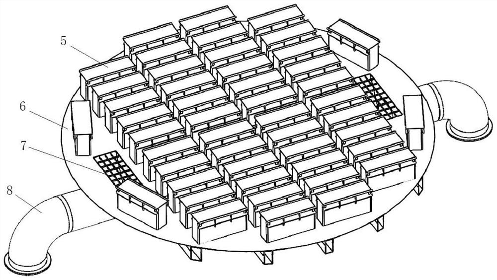
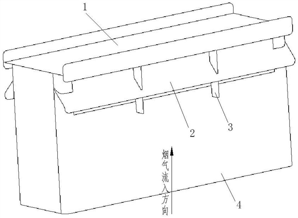
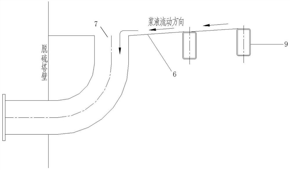
[0034] An alloy steel plate with a high middle and low sides is set below the circulating spray layer as the liquid collecting pan 6, and the rising air cap 5 is welded on the upper part of the liquid collecting pan 6, and the outer walls of every two rising air caps 5 are connected to each other to form a lateral support; The liquid discharge port 7 is arranged on both sides of the liquid collection tray 6, and the cross section of the liquid discharge port 7 is ...


PUM


Abstract

The invention relates to a novel liquid collector device which comprises gas rising caps, a liquid collecting tray and a liquid discharging pipe. The liquid collecting tray is of a two-way ramp liquiddischarging structure with a high middle part and two low sides. The gas rising caps are welded to the hole positions of the liquid collecting tray and each comprise a top plate, flow guide plates, top plate supports and side baffles, the side baffles define an airflow channel, the top plate is welded to the tops of the side baffles, the flow guide plates are welded to the hole positions of the two sides of the side baffles, and the top plate supports are welded between the top plate and the side baffles. Liquid outlets are formed in the lower parts of the two lower sides of the liquid collecting tray and are connected with liquid discharging pipes. The novel liquid collector device has the beneficial effects that the gas rising caps are arranged, the characteristics of gas-liquid two-phase flow in flue gas are fully utilized, the proper aperture ratio of the liquid collecting tray is selected, the gas rising caps are uniformly arranged on the liquid collecting tray, the running resistance of a system is reduced, and a good flue gas removal effect can be achieved.

Description

technical field [0001] The invention relates to the field of coal-fired power plant desulfurization, chemical plant desulfurization, ship desulfurization, etc. that need to realize gas-liquid two-phase separation, and in particular relates to a metal liquid collector device for ammonia desulfurization. Background technique [0002] In the environmental protection facilities of coal-fired boilers, in order to realize the desulfurization partition design in the absorption tower, a liquid collector is usually installed under the spray layer to discharge the reacted slurry to the outside of the tower. [0003] A conventional wet flue gas desulfurization tower includes a concentration section, a desulfurization section, a washing section and a demister. The desulfurization section mainly absorbs SO in the flue gas by spraying ammonia water slurry. 2 , the washing section mainly sprays circulating water and washes the flue gas. In order to fully separate the desulfurized or washe...

Claims


Application Information

Patent Timeline
IPC IPC(8): B01D45/08B01D53/18B01D53/14
CPCB01D45/08B01D53/1481B01D53/18B01D2252/102B01D2258/0283
Inventor 李建惠胡达清刘文榉钟莎唐飞翔姜雅洲冯立波徐承亮刘寒梅柯昌华
Owner ZHEJIANG TIANDI ENVIRONMENTAL PROTECTION TECH CO LTD
Features
  • R&D
  • Intellectual Property
  • Life Sciences
  • Materials
  • Tech Scout
  • Unparalleled Data Quality
  • Higher Quality Content
  • 60% Fewer Hallucinations
Learn More