Cleaning device for air compressor cooling system

A cooling system and cleaning device technology, applied in mechanical equipment, cleaning hollow objects, machines/engines, etc., can solve problems affecting system operation, high corrosion, small heat exchange pipe diameter, etc., and achieve the effect of ensuring the cleaning effect

Pending Publication Date: 2020-09-01
深圳市诚至臻科技有限公司
View PDF0 Cites 2 Cited by
  • Summary
  • Abstract
  • Description
  • Claims
  • Application Information

AI Technical Summary

Problems solved by technology

In terms of cooling water, due to its high corrosiveness, it is easy to cause blockage of heat exchange tubes, corrosion of unit and pipeline accessories, and affect the normal operation of the system. Generally, the cleaning of the cooler of the air compressor is mainly done manually. The cooling water of the air compressor is Parallel connection, due to the small pipe diameter, and the heat exchange pipe diameters of the air cooling section cooler of the air compressor and the cooling water section of the cooling oil are different, the heat exchange pipe diameter of the air compressor cooler is small, generally 6mm and 8mm, which brings great trouble to the cooler cleaning

Method used


Image

  • Cleaning device for air compressor cooling system
  • Cleaning device for air compressor cooling system

Examples


Embodiment Construction

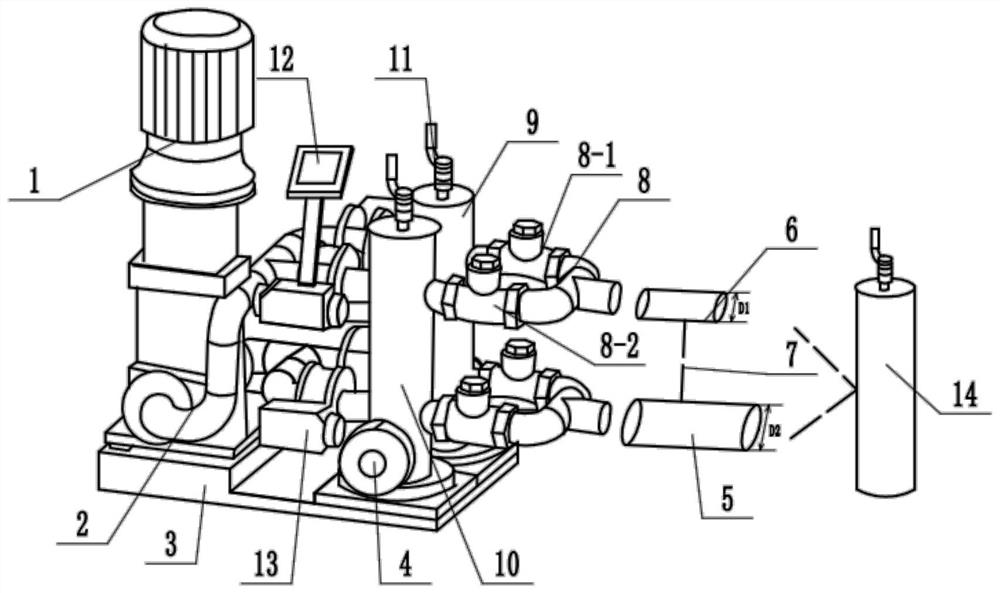
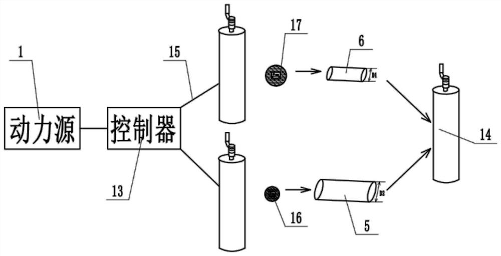
[0011] like Figure 1-2 As shown, the device mainly includes a power pump 1, a first-class ball machine 9, a second-class ball machine 10, and a ball catcher 14. The output end of the power water pump 1 is communicated with a ball-serving power pipe 2, and the ball-serving power pipe 2 is another One end is connected to the first type of ball machine 9 and the second type of ball machine 10, the first type of ball machine 9 and the second type of ball machine 10 are connected to a collection pipe 8, the other end of the collection pipe 8 Correspondingly connected to the air pressure cooling pipe 6 and the oil pressure cooling pipe 5, the other ends of the air pressure cooling pipe 6 and the oil pressure cooling pipe 5 are connected to the ball catcher 14; the power water pump 1 , the first-class serving machine 9, the second-class serving machine 10, and the ball catcher 14 are all independently installed on the base plate 3, and the tops of the first-class serving machine 9 a...


PUM


Abstract

The invention discloses a cleaning device for an air compressor cooling system. The device mainly comprises a power water pump, a first-class ball serving machine, a second-class ball serving machineand a ball catcher. The output end of the power water pump is provided with a ball serving power pipe in a communicating mode, and the other end of the ball serving power pipe is connected to the first-class ball serving machine and the second-class ball serving machine. The first-class ball serving machine and the second-class ball serving machine are connected with collecting pipes, and the other ends of the collecting pipes correspondingly communicate with an air compression cooling pipe and an oil compression cooling pipe repectively. The other end of the air compression cooling pipe and the other end of the oil compression cooling pipe are connected to the ball catcher. The cleaning device for the air compressor cooling system has the beneficial effects that two ball serving machinesare arranged, double ball serving through one power source is designed, rubber balls with two pipe diameters enter the two ball serving machines respectively, the air compression cooling pipe and theoil compression cooling pipe are arranged in parallel and move in cooperation with the rubber balls cleaned by the air compression cooling pipe and the oil compression cooling pipe, and thus the cleaning independence is guaranteed; and the same ball catcher collects returned balls, and thus the cleaning effect of a cooler is guaranteed.

Description

technical field [0001] The invention belongs to the technical field of cooling system cleaning, and in particular relates to a cooling system cleaning device of an air compressor. Background technique [0002] Dust, moisture, bacteria, oxygen and certain harmful acid gases in the atmosphere continuously enter the cooling system of the heat exchange system from the cooling tower. Over time, the cooling system will produce dirt, rust, rust residue and biological sticky produced by the continuous reproduction of microorganisms. Mud will block the pipes and reduce the cooling capacity, waste electric energy, and even shut down at overpressure, which will directly damage the air compressor and shorten the service life of the air compressor. The cleaning and maintenance of the cooler mainly refers to the cleaning and maintenance of the circulating water system. The water system of the air compressor is mainly the cooling water system, in which the cooling water system mainly relie...

Claims


Application Information

Patent Timeline
Patent Type & Authority Applications(China)
IPC IPC(8): F04B39/06F04B39/00B08B9/055B08B13/00
CPCB08B9/0552B08B13/00F04B39/00F04B39/064
Inventor 马铭赵成刚李富山
Owner 深圳市诚至臻科技有限公司
Why Eureka
Try Eureka