Novel optical fiber torsion sensor insensitive to temperature, stress and light source intensity

A technology of torsion sensor and optical fiber, applied in the direction of converting sensor output, using optical devices to transmit sensing components, instruments, etc., can solve problems such as the influence of light source intensity, and achieve the effects of simple production, low cost, and accurate measurement

Pending Publication Date: 2020-09-04
CHINA JILIANG UNIV
View PDF0 Cites 3 Cited by
  • Summary
  • Abstract
  • Description
  • Claims
  • Application Information

AI Technical Summary

Problems solved by technology

[0003] Aiming at the defects or improvement needs of the prior art, the present invention provides the design and preparation method of a novel fiber optic torsion sensor that is insensitive to temperature, stress, and light source intensity. The measurement eliminates the left and right drift of the spectrum caused by temperature and stress, and eliminates the influence of the up and down drift of the spectrum caused by the change of light source intensity through the calculation of the extinction ratio.

Method used


Image

  • Novel optical fiber torsion sensor insensitive to temperature, stress and light source intensity
  • Novel optical fiber torsion sensor insensitive to temperature, stress and light source intensity
  • Novel optical fiber torsion sensor insensitive to temperature, stress and light source intensity

Examples


Embodiment Construction

[0021] In order to make the object, technical solution and advantages of the present invention clearer, the present invention will be further described in detail below in conjunction with the accompanying drawings and embodiments. It should be understood that the specific embodiments described here are only used to explain the present invention, not to limit the present invention. In addition, the technical features involved in the various embodiments of the present invention described below can be combined with each other as long as they do not constitute a conflict with each other.

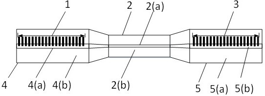
[0022] The optical fiber torsion sensor provided by the present invention includes two sets of reflective structure groups and a cone region; wherein the two reflective structure groups are located at both ends of the cone region; the present invention will be further described below in conjunction with the accompanying drawings and practical examples.

[0023] Implementation of the provided fib...


PUM

PropertyMeasurementUnit
lengthaaaaaaaaaa
diameteraaaaaaaaaa
diameteraaaaaaaaaa

Abstract

The invention discloses a novel optical fiber torsion sensor insensitive to temperature, tension and light source intensity and a preparation method thereof. The sensor is composed of three parts along the length direction, wherein the first part is composed of a plurality of femtosecond laser etching lines which are equally spaced and equal in length and are perpendicular to the axial direction of the optical fiber, and a group of reflection structures are formed. The second part is a conical area part, and the third part is completely the same as the first part. The first part and the thirdpart form an FP interference cavity, wherein the cavity length of the FP interference cavity is the distance between the two groups of reflection structures, and when the optical fiber is twisted, thecavity length of the interference structure formed by the two groups of reflection structures is not changed, but the polarization direction is changed, so that the interference condition of the interference structure is damaged, and the extinction ratio of a reflection spectrum is reduced. The torsion angle is calculated by measuring the variation of the extinction ratio of the reflectance spectrum. The design of the sensor can eliminate the interference of temperature, stress and light source intensity on the measurement result.

Description

technical field [0001] The invention belongs to the field of optical fiber sensing and measurement, and more specifically relates to the invention and preparation of a novel optical fiber torsion angle sensor. Background technique [0002] The fiber optic torsion sensor has the advantages of high sensitivity, fast response, and no interference from electromagnetic fields. In recent years, it has been effectively applied in manufacturing industry, energy industry, medical treatment and other fields. Common optical fiber torsion sensors based on the principles of Bragg gratings, long-period gratings, and intermode interference have the advantages of small size, light weight, simple use, and good portability, and are currently widely used. However, since the refractive index of the quartz material in the optical fiber sensor is affected by the ambient temperature and stress, there are generally disadvantages such as low torsional sensitivity, inaccuracy, and susceptibility to ...

Claims


Application Information

Patent Timeline
Patent Type & Authority Applications(China)
IPC IPC(8): G01B11/26G01D5/353
CPCG01B11/26G01D5/35354G01D5/3538
Inventor 陈琦高峰王东宁王海龙王兆坤徐贲
Owner CHINA JILIANG UNIV
Why Eureka
Try Eureka