
Optical sensor packaging structure and electronics

A technology of optical sensor and packaging structure, applied in the direction of sensor, circuit, medical science, etc., can solve the problem of incomplete curing of glue at the bottom of the potting glue layer

Active Publication Date: 2022-03-25
QINGDAO GOERTEK INTELLIGENT SENSOR CO LTD
View PDF0 Cites 0 Cited by
  • Summary
  • Abstract
  • Description
  • Claims
  • Application Information

AI Technical Summary

Problems solved by technology

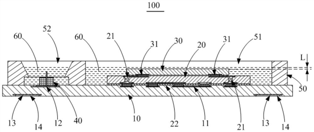
[0004] The main purpose of the present invention is to provide an optical sensor packaging structure and electronic equipment, aiming to solve the problem of incomplete curing of the bottom glue due to the large thickness of the potting adhesive layer, thereby improving the reliability of the optical sensor packaging structure

Method used


Image

  • Optical sensor packaging structure and electronics
  • Optical sensor packaging structure and electronics
  • Optical sensor packaging structure and electronics

Examples


Embodiment Construction

[0026] The technical solutions in the embodiments of the present invention will be clearly and completely described below with reference to the accompanying drawings in the embodiments of the present invention. Obviously, the described embodiments are only a part of the embodiments of the present invention, but not all of the embodiments. Based on the embodiments of the present invention, all other embodiments obtained by those of ordinary skill in the art without creative efforts shall fall within the protection scope of the present invention.

[0027] It should be noted that all directional indications (such as up, down, left, right, front, back...) in the embodiments of the present invention are only used to explain the relationship between various components under a certain posture (as shown in the accompanying drawings). The relative positional relationship, the movement situation, etc., if the specific posture changes, the directional indication also changes accordingly. ...


PUM

PropertyMeasurementUnit
elongation at breakaaaaaaaaaa

Abstract

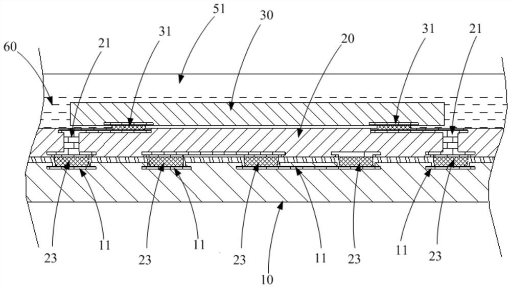
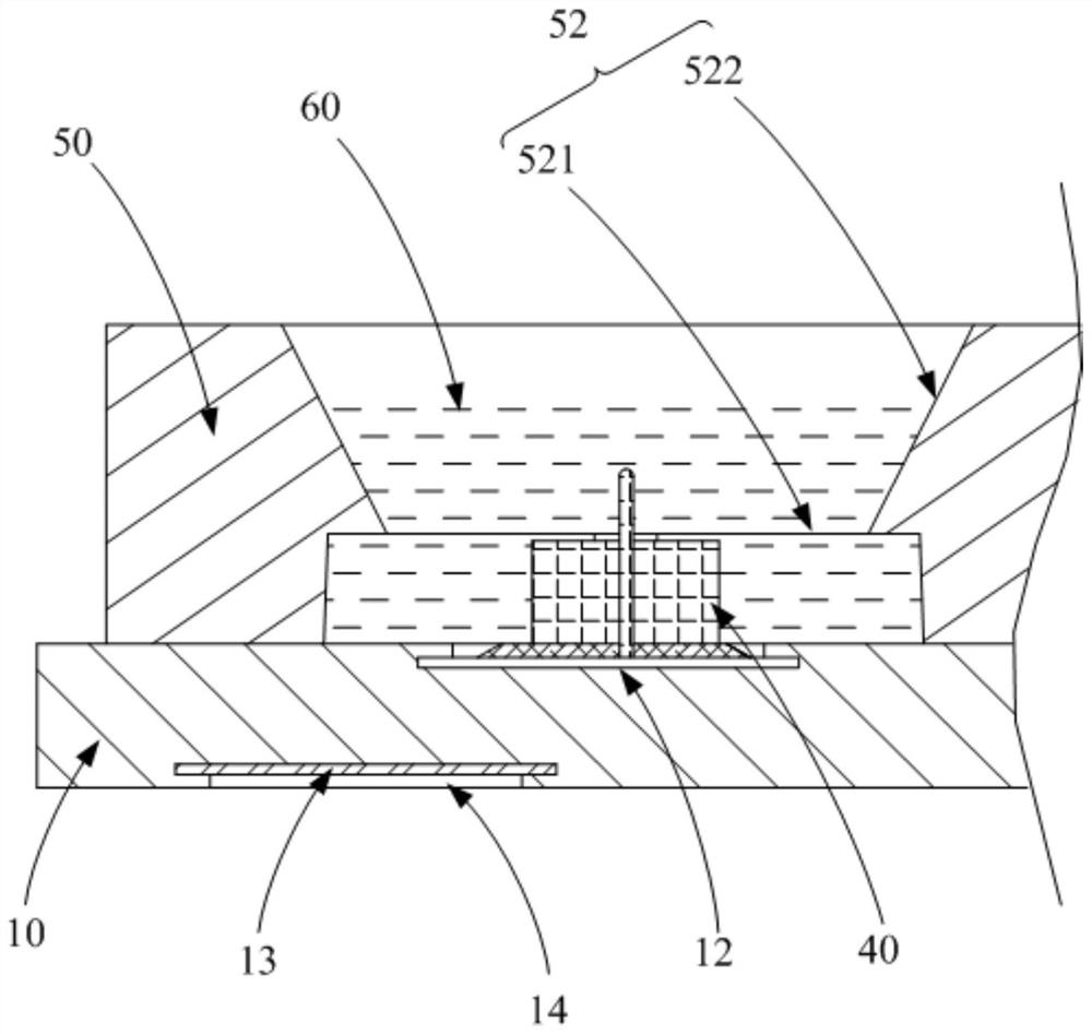
The invention discloses an optical sensor packaging structure and electronic equipment. Wherein, the optical sensor packaging structure includes: a substrate; a signal processing chip, the signal processing chip is arranged on the surface of the substrate, the signal processing chip is provided with a conductive through hole, and the signal processing chip passes through the conductive through hole. a hole is electrically connected to the substrate; a photodiode is arranged on the surface of the signal processing chip facing away from the substrate, and is electrically connected to the substrate through the conductive through hole; and a potting glue layer, the potting adhesive layer covers the signal processing chip and the photodiode, and the elongation at break of the potting adhesive layer is greater than 40%. The technical scheme of the present invention can solve the problem of incomplete curing of the bottom glue due to the large thickness of the potting glue layer, thereby improving the reliability of the optical sensor packaging structure.

Description

technical field [0001] The present invention relates to the technical field of system level packaging, in particular to an optical sensor packaging structure and an electronic device. Background technique [0002] Optical sensors (such as heart rate and blood oxygen sensors) generally include photodiodes and light-emitting diodes. The light emitted by the light-emitting diodes is reflected by the capillaries in the human tissue and then irradiated to the photodiodes, and the user is measured by the change law of the photocurrent AC current component. heart rate or blood oxygen. In the related art, the optical sensor packaging structure includes a substrate and a photodiode. The photodiode is usually electrically connected to the substrate by wire bonding. When the photodiode is sealed with a potting glue, the potting glue needs to completely cover the photodiode and the photodiode. Its lead will make the thickness of the potting glue layer larger. When the potting glue is c...

Claims


Application Information

Patent Timeline
Patent Type & Authority Patents(China)
IPC IPC(8): H01L25/16H01L23/31H01L23/48A61B5/024A61B5/1455
CPCH01L25/167H01L23/481H01L23/3107A61B5/02427A61B5/1455A61B2562/00H01L33/62H01L23/3185H01L31/02005H01L31/0203H01L31/167H01L23/3121H01L24/16H01L24/17H01L2224/16145H01L2224/16227H01L2224/17181H01L2924/12043
Inventor 汪奎王德信孙艳美宋海强
Owner QINGDAO GOERTEK INTELLIGENT SENSOR CO LTD
Learn More