Blade structure of centrifugal blower

A centrifugal blower and blade technology, applied in mechanical equipment, machines/engines, liquid fuel engines, etc., can solve problems such as noise and reduced blowing efficiency of fans, and achieve the effects of suppressing turbulence, improving inflow state, and improving inflow state.

Pending Publication Date: 2020-09-11
SHINKO IND CO LTD (JP)
View PDF1 Cites 0 Cited by
  • Summary
  • Abstract
  • Description
  • Claims
  • Application Information

AI Technical Summary

Problems solved by technology

[0007] like this, in Figure 4 Among them, the cross sections of the blade b along the cutting lines AA', BB', and CC' have the same shape, and the same blade cross-sectional shape is continuous in the width direction of the blade, which is easy to manufacture. However, air turbulence occurs in the flow path between the leading edge of the blade and the blade, which reduces the blowing efficiency of the fan and generates noise due to wind noise.

Method used


Image

  • Blade structure of centrifugal blower
  • Blade structure of centrifugal blower
  • Blade structure of centrifugal blower

Examples


Embodiment 1

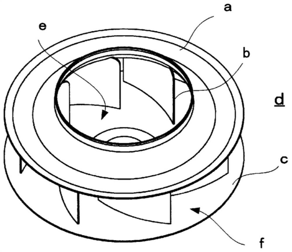
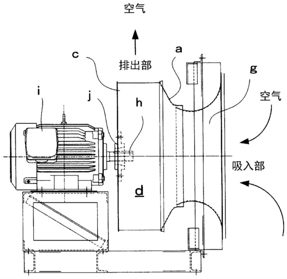
[0035] Preferred Embodiment 1 of the blade structure of the centrifugal blower of the present invention will be described, Figure 5 The impeller 4 of the centrifugal blower is the same as before figure 2 The structure as shown is arranged in the blast chamber in the air conditioner.

[0036] First, assemble from Figure 5 The blade 3 of the impeller 4 in Embodiment 1, which is combined with the fan suction port 7, will be described first.

[0037] The blades 3 of the impeller 4 are arranged obliquely at equal intervals from the suction portion 5 toward the outer peripheral discharge portion 6 between the back plate 1 and the shroud 2 .

[0038] The blade lower side 31 of the blade 3 is a shape along the back plate 1, the blade upper side 33 is a shape along the inner surface of the shroud 2, and the vicinity of the suction part 5 that cuts off the air on the blade upper side 33 has a raised protrusion. shape part 332 .

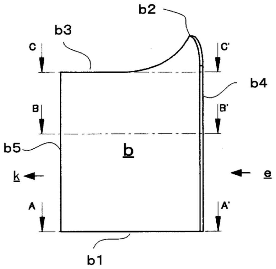
[0039] And, the blade leading edge portion 32 that...

Embodiment 2

[0043] In the present invention, by adjusting the width of the belt at the center of the vertical width of the blade 3 in the impeller 4 of the centrifugal blower, the twisted shapes Y1 and Y2 near the front edge can be kept as they are, and high efficiency and low noise can be maintained. and the blade width (Z) can be easily changed. Therefore, it is possible to design and manufacture a centrifugal fan corresponding to the designed air volume.

[0044] Here, refer to Figure 9 and Figure 10 Example 2 in which the vertical width of the impeller 4' is changed to a blade width corresponding to the blowing volume will be described.

[0045] Figure 9 It is the perspective view of the impeller 4' of embodiment 2, as Figure 10 As shown, the twisted shapes Y1 and Y2 near the front edge of the blade 3 are the same as those in Example 1, and compared with the conventional partially cylindrical blade, the blowing efficiency is improved and the noise is also reduced. That is, wh...


PUM


Abstract

The invention provides a blade structure of a centrifugal blower, which can obtain blowing efficiency and noise reduction effect. A centrifugal blower in which a plurality of blades are erected between a back plate and a shroud disposed at a predetermined interval from the back plate, the vicinity of the leading edge portions of the blades in the blade rotation direction on the back plate side andthe shroud side being in a twisted shape that curves in the outer circumferential direction in the vicinity of the back plate and the shroud of the blades, and the shroud being disposed at a predetermined interval from the back plate. Subsequent parts, connected with the torsion shape, of the blades are the same cylindrical plane, the shape of the edge of the front edge part is a bending shape with a concave central part, and the central part in the width direction of the blades is also the same cylindrical plane from the front edge part to the subsequent parts.

Description

technical field [0001] The present invention relates to a blade structure of a centrifugal blower used in an air conditioner or the like. Background technique [0002] Conventional centrifugal blowers such as multi-blade fans and centrifugal fans (Japanese: プラグファン) are composed of the suction part of the impeller with multiple blades erected between the shroud on the air suction side and the back plate on the motor side and the fan suction port. The structure uses the rotation of the motor to rotate the impeller to blow air. [0003] The centrifugal blower is often used for air blowing of air-conditioning equipment as shown in Patent Document 1, and a conventional common centrifugal fan is shown in the figure. Figure 1 ~ Figure 4 explained in . [0004] like figure 2 shown, is figure 1 The structure of the combination of the suction part e of the impeller d including the shroud a, blade b, and back plate c and the fan suction port g. The motor shaft h is fastened to t...

Claims


Application Information

Patent Timeline
Patent Type & Authority Applications(China)
IPC IPC(8): F04D29/30F04D29/66
CPCF04D29/30F04D29/666F04D29/667
Inventor 上田和成日置达也
Owner SHINKO IND CO LTD (JP)
Why Eureka
Try Eureka