Vaporization device of liquefied gas storage tank

A technology of liquefied gas and vaporization device, which can be used in gas processing/storage purposes, gas/liquid distribution and storage, fixed-capacity gas storage tanks, etc. The effect of footprint and volume reduction

Pending Publication Date: 2020-09-11
苏州料金气体有限公司
View PDF0 Cites 0 Cited by
  • Summary
  • Abstract
  • Description
  • Claims
  • Application Information

AI Technical Summary

Problems solved by technology

But this mode virtually causes heat loss, which is a waste of energy

Method used


Image

  • Vaporization device of liquefied gas storage tank

Examples


Embodiment

[0021] The preferred embodiments of the present invention will be further described below in conjunction with the accompanying drawings.

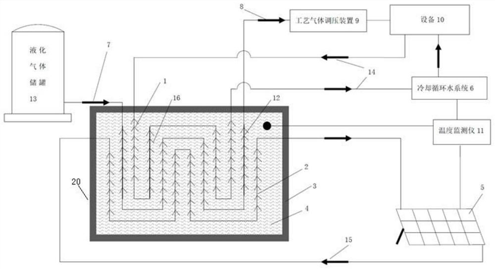
[0022] like figure 1 As shown, a vaporization device for a liquefied gas storage tank includes a vaporizer chamber 20, the inner wall of the vaporizer chamber 20 is provided with a heat insulating layer 3, a phase change material 4 is arranged in the vaporizer chamber 20, and a vaporizer chamber 20 is also provided with There are multiple sets of heat exchange devices, at least two sets of heat exchange devices, including the first heat exchange device 12 and the second heat exchange device 2, the input end of the first heat exchange device 12 is connected to the liquefied gas storage through the low-temperature liquefied gas input pipeline 7 The tank 13, the output end of the first heat exchange device 12 is connected to the gas consumption equipment 10 through the process gas output pipeline 8, the input end and output end of the second h...


PUM


Abstract

The invention discloses a vaporization device of a liquefied gas storage tank. The vaporization device comprises a vaporizer containing cavity, a heat insulation layer is arranged on the inner wall ofthe vaporizer containing cavity, a phase-change material is arranged in the vaporizer containing cavity, a plurality of groups of heat exchange devices are also arranged in the vaporizer containing cavity, at least two groups of the heat exchange devices are provided and comprise a first heat exchange device and a second heat exchange device, the input end of the first heat exchange device is connected with the liquefied gas storage tank through a low-temperature liquefied gas input pipeline, the output end of the first heat exchange device is connected with gas equipment through a process gas output pipeline, the input end and the output end of the second heat exchange device are connected with a solar heat supply system through a second pipeline, and a heat transfer medium is arranged in the second pipeline. The phase change energy storage technology is used, so that the volume of the vaporization device is greatly reduced, the vaporization efficiency is improved, the secondary utilization of redundant heat generated during equipment heat dissipation is realized, a new idea is added for energy conservation and emission reduction of a factory, and the energy consumption of the factory is reduced.

Description

technical field [0001] The invention relates to a vaporizer, in particular to a vaporization device for a liquefied gas storage tank. Background technique [0002] In the prior art, the evaporators equipped with traditional liquefied gas storage tanks are used to vaporize the liquefied gas by freely absorbing the heat in the ambient air around the evaporator in a free state. In winter, due to the relatively low temperature of the surrounding environment, the vaporizer does not absorb enough heat from the surrounding environment, resulting in insufficient vaporization, which leads to unstable gas consumption of the back-end equipment. In addition, in winter, the internal temperature of the carburetor caused by insufficient vaporization capacity is too low, which will also cause a lot of ice cubes to condense and freeze on the outer surface of the carburetor. . Traditional vaporizers freely absorb the heat in the ambient air around the vaporizer through the free state. This ...

Claims


Application Information

Patent Timeline
Patent Type & Authority Applications(China)
IPC IPC(8): F17C7/04F17C9/02C09K5/06
CPCC09K5/063F17C7/04F17C9/02F17C2223/0153F17C2227/0316F17C2227/033F17C2260/046Y02E60/32Y02P90/45
Inventor 王峰周林华赵海琴
Owner 苏州料金气体有限公司
Why Eureka
Try Eureka