
A power-changing locking device

A technology of locking devices and electric locks, which is applied to batteries, circuits, charging stations, etc., can solve problems such as inability to replace batteries by manual operation, easy fatigue damage of bolts, and falling of battery packs, so as to avoid the risk of failure and improve reliability , The effect of quick battery replacement

Active Publication Date: 2021-10-26
ZHEJIANG JIZHI NEW ENERGY AUTOMOBILE TECH CO LTD
View PDF10 Cites 0 Cited by
  • Summary
  • Abstract
  • Description
  • Claims
  • Application Information

AI Technical Summary

Problems solved by technology

However, the operation of the power exchange method also faces some difficulties
First of all, in order to ensure a certain cruising range, the vehicle power battery pack needs to increase the weight of the battery when the capacity density of the existing battery is low, so it is impossible to manually replace the battery, and certain professional equipment is required; Connected by a locking mechanism similar to the opening and closing parts, it is necessary to ensure the accuracy and reliability of positioning and meet the needs of multiple disassembly and assembly
[0005] At present, most of the quick battery replacement methods use battery replacement from the bottom of the car. At present, there are two locking methods for bottom battery replacement: one is to use a linkage locking mechanism, which is easy to operate but prone to failure, easy to get stuck, unable to disassemble and cannot be installed If there is a serious fault, the battery pack will fall; one is to use bolts to lock. This method has a simple structure, but the weight of the battery is borne by the bolts, and the torque is relatively large. In the case of cyclic disassembly of the bolts, the bolts are prone to fatigue damage

Method used


Image

  • A power-changing locking device
  • A power-changing locking device

Examples


Embodiment 1

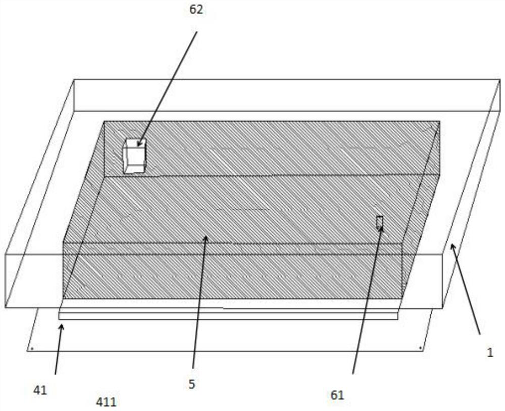
[0032] Such as figure 1 As shown, this embodiment provides a battery swap locking device, including a battery pack bracket 1, a locking device, a driving device 3 and a battery swap platform, the battery pack bracket 1 is rectangular, and the battery pack bracket 1 Used to hold the battery pack.

[0033] Such as figure 1 As shown, the locking device includes a locking pin 21 and a locking lever, one end of the locking pin 21 is connected to the battery pack bracket 1, and the end of the locking pin 21 away from the battery pack bracket 1 is provided with a recess. Groove 211, the opening of the groove 211 is set upward, the lock bar includes a horizontal bar 221 and a vertical bar 222, the horizontal bar 221 is engaged with the groove 211, and the vertical bar 222 is arranged on the horizontal bar 222 Inside the bar 221 , the vertical bar 222 is used to support the horizontal bar 221 .

[0034] Such as figure 1 As shown, the driving device 3 includes a transmission member ...

Embodiment 2

[0040] This embodiment 2 provides a battery swap locking device, including a battery pack bracket 1, a locking device, a driving device 3 and a battery swap platform, the battery pack bracket 1 is rectangular, and the battery pack bracket 1 is used for Secure the battery pack.

[0041]Specifically, the locking device includes a locking pin 21 and a locking lever, one end of the locking pin 21 is connected to the battery pack bracket 1 , and a recess is provided at the end of the locking pin 21 away from the battery pack bracket 1 . Groove 211, the opening of the groove 211 is set upward, the lock bar includes a horizontal bar 221 and a vertical bar 222, the horizontal bar 221 is engaged with the groove 211, and the vertical bar 222 is arranged on the horizontal bar 222 Inside the bar 221, the vertical bar 222 is used to support the cross bar 221

[0042] Specifically, the driving device 3 includes a transmission member 31, a rotating shaft 32 and a fastening mechanism 33. The...

Embodiment 3

[0049] This embodiment provides an electric vehicle, including 5 battery packs and 8 battery swap locking devices. The battery swap locking device includes a battery pack bracket 1, a locking device, a drive device 3, and a battery swap platform. The battery pack 5 is arranged in the battery pack bracket 1, and the battery pack bracket 1 is used to fix the battery pack 5, and the battery pack bracket 1 is rectangular.

[0050] Specifically, the locking device includes a locking pin 21 and a locking lever, one end of the locking pin 21 is connected to the battery pack bracket 1 , and a recess is provided at the end of the locking pin 21 away from the battery pack bracket 1 . Groove 211, the opening of the groove 211 is set upward, the lock bar includes a horizontal bar 221 and a vertical bar 222, the horizontal bar 221 is engaged with the groove 211, and the vertical bar 222 is arranged on the horizontal bar 222 Inside the bar 221 , the vertical bar 222 is used to support the h...


PUM


Abstract

The invention relates to the technical field of battery replacement, in particular to a locking device for battery replacement, including a battery pack bracket, a locking device, a driving device and a battery swapping platform; the battery pack bracket is used to fix the battery pack; the locking device It includes a locking pin and a locking bar, one end of the locking pin is connected to the battery pack bracket, and the other end of the locking pin is engaged with the locking bar; the driving device includes a transmission member and a rotating shaft, and the The transmission member is used to control the movement of the locking pin, and the transmission member is fixed on the rotating shaft, and the rotating shaft is fixed on the battery pack bracket; the power exchange platform is used to control the lifting of the battery pack. The battery replacement locking device of the present invention adopts a pin-type fixing method, avoids the failure risk of the locking method, improves the reliability of the locking device, has a simple structure, low cost, can realize quick battery replacement, and saves battery replacement time.

Description

technical field [0001] The invention relates to the technical field of battery replacement, in particular to a battery replacement locking device. Background technique [0002] With the development of the economy and the progress of the society, people pay more and more attention to the living environment around them, and their awareness of protecting the environment is getting stronger and stronger. Therefore, the rational use of many environmentally friendly and clean energy is gradually placed on the agenda. As an important tool for people to travel, traditional fuel vehicles have always been concerned about their exhaust emissions. The exhaust emissions cause a lot of pollution. The emergence of pure electric energy vehicles has solved the environmental problems of exhaust emissions from traditional fuel vehicles. Pure electric energy vehicles have the huge advantage of being clean and environmentally friendly with zero emissions, and have been valued by many countries in...

Claims


Application Information

Patent Timeline
Patent Type & Authority Patents(China)
IPC IPC(8): B60L53/80H01M50/249H01M50/262
CPCB60S5/06H01M2220/20Y02E60/10Y02T10/70Y02T10/7072
Inventor 徐现振郑宇翔闵继超徐爱平陈君
Owner ZHEJIANG JIZHI NEW ENERGY AUTOMOBILE TECH CO LTD
Learn More