
Gas-liquid circulation system of airlift fermentation tank

An air-lift fermenter and circulation system technology, which is applied in the field of air-lift fermenter gas-liquid circulation system, can solve the problems of slow temperature rise, uneven liquid mixing, untimely temperature adjustment, etc., so as to increase the contact area and promote activities. Efficiency, the effect of increasing the contact area

Active Publication Date: 2020-09-15
ZHONGNONGXINKE SUZHOU ORGANIC RECYCLING RES INST CO LTD
View PDF9 Cites 0 Cited by
  • Summary
  • Abstract
  • Description
  • Claims
  • Application Information

AI Technical Summary

Problems solved by technology

[0003] The air-lift fermenter is mainly ventilated from the air duct to the bottom of the fermenter to make the liquid flow and mix in the fermenter. However, due to the limitation of the ventilation volume and the efficiency of the ventilation direction, it has the disadvantage of uneven liquid mixing, which often leads to temperature , dissolved oxygen, pH and other data test results are delayed, which leads to untimely feeding and oxygen addition; in addition, because the fermenter consumes a lot of energy for heating and the temperature rises slowly, the problems of high cost and untimely temperature adjustment are also urgent. Need to solve

Method used


Image

  • Gas-liquid circulation system of airlift fermentation tank
  • Gas-liquid circulation system of airlift fermentation tank
  • Gas-liquid circulation system of airlift fermentation tank

Examples


Embodiment Construction

[0018] The technical solutions of the present invention will be further described below in conjunction with the accompanying drawings and embodiments.

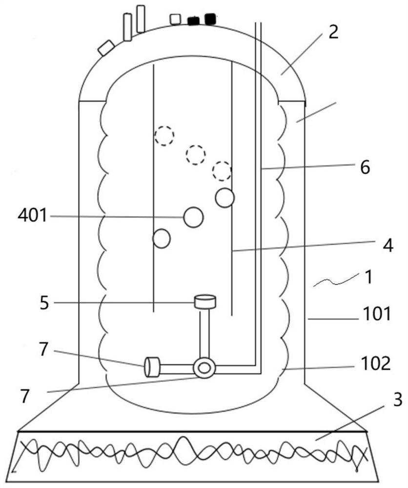
[0019] like figure 1 The air-lift fermenter gas-liquid circulation system shown includes:

[0020] A heating fermenter, the heating fermenter includes a fermenter body 1 and a tank cover 2, the bottom of the fermenter body 1 is provided with a heating base 3, and the fermenter body 1 is formed as a hollow tank by an insulating outer wall 101 and an insulating inner wall 102 The liquid material is arranged in the hollow area, and the internal liquid material can be heated by heating the base 3. The fermentation chamber is formed in the heat preservation inner wall 102, and the fermentation chamber is heated by heating the liquid material. This heating method is more uniform and reliable. control.

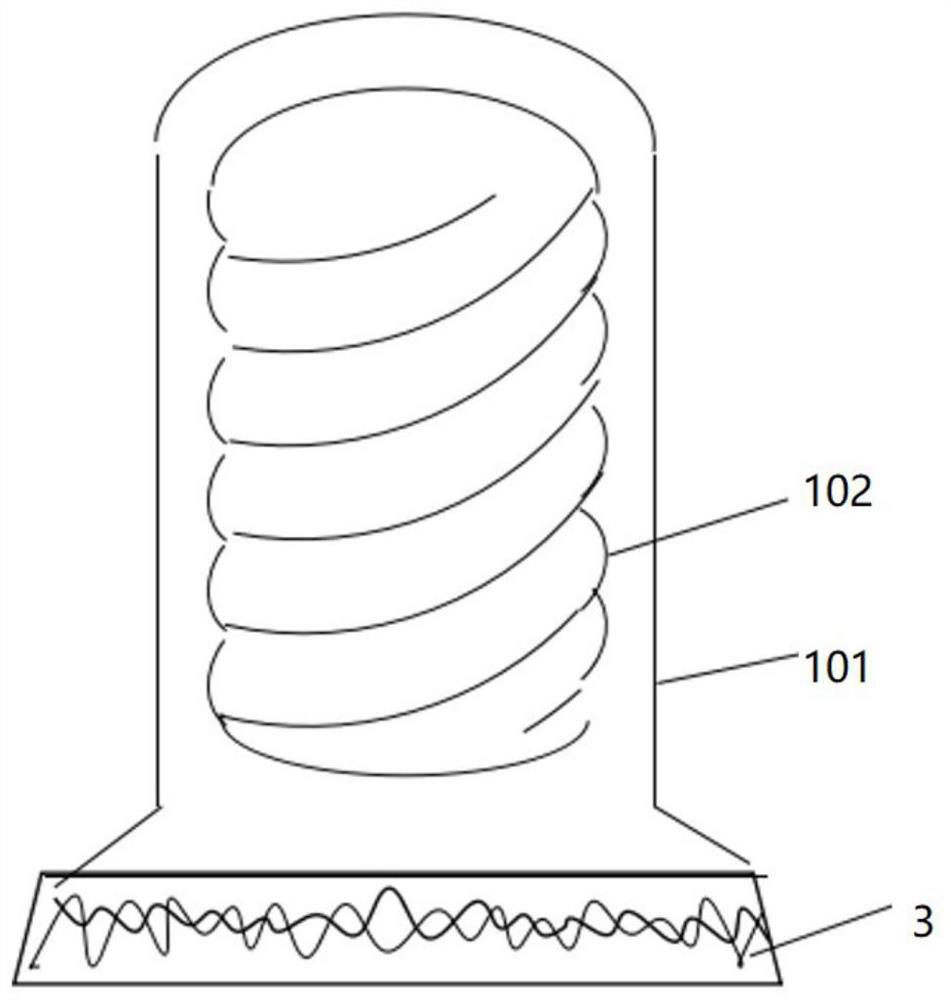
[0021] like figure 2 As shown, the heat preservation inner wall 102 is a spiral internal thread structure, which can increase t...


PUM


Abstract

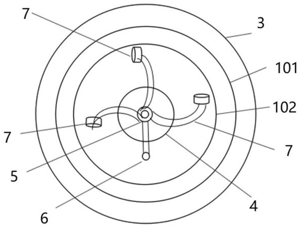
The present invention discloses a gas-liquid circulation system of an airlift fermentation tank. The gas-liquid circulation system comprises: a heating fermentation tank, an air inlet circulation assembly and a vertical air spraying head; the heating fermentation tank comprises a fermentation tank body and a tank cover, the bottom of the fermentation tank body is provided with a heating base, thefermentation tank body is a hollow tank body formed by a thermal insulation outer wall and a thermal insulation inner wall, a liquid material is arranged in the hollow area, and a fermentation cavityis formed in the thermal insulation inner wall; the air inlet circulation assembly comprises a circulation inner wall which is arranged in the center of the inner side of the tank cover and extends tothe bottom of the fermentation cavity, and a plurality of circulation holes which spirally ascend are formed in the circulation inner wall; the vertical air spraying head is arranged below the circulation inner wall and sprays air to the upper direction, and the vertical air spraying head extends out of the heating fermentation tank through a main air inlet pipe; and the tank cover is provided with a detection opening, an air inlet and outlet opening and a material feeding and supplementing opening. According to the system, the spirally ascending circulation holes and the threaded inner wallare matched with an air injection device to form circulation in the fermentation cavity, liquid mixing of the inner layer and the outer layer of the circulation inner wall is enhanced, the air inflowis increased, and liquid in the fermentation tank can be rapidly and evenly mixed.

Description

technical field [0001] The invention relates to the technical field of fermentation engineering, in particular to an air-lift fermentation tank gas-liquid circulation system. Background technique [0002] The current fermenter is mainly divided into two types, one is a mechanical stirring fermenter, and the other is an air-lift fermenter. The air-lift fermenter is a new type of bioreactor that was developed and applied in the 1970s. It is widely used in large-scale cultivation of aerobic microorganisms. The airlift fermenter is fully enclosed, with good sealing performance, and is not easy to be contaminated with bacteria in microbial cultivation; it has a simple structure and is easy to operate. After connecting the detection port instrument, it can be directly The data is derived from the machine; the air-lift fermenter saves about 70-80% of electricity on average than the stirred fermenter, which greatly reduces energy consumption. [0003] The air-lift fermenter is main...

Claims


Application Information

Patent Timeline
Patent Type & Authority Applications(China)
IPC IPC(8): C12M1/00C12M1/38C12M1/36C12M1/34C12M1/12C12M1/04
CPCC12M23/02C12M23/38C12M29/04C12M29/06C12M29/08C12M41/12C12M41/26C12M41/32Y02W30/40
Inventor 李季郝尉妤
Owner ZHONGNONGXINKE SUZHOU ORGANIC RECYCLING RES INST CO LTD
Learn More