A waste collection device for CNC machine tools that is convenient for chip removal

A waste collection, CNC machine tool technology, applied in metal processing machinery parts, metal processing equipment, maintenance and safety accessories, etc., can solve the problems of trouble, long processing time, delay time, etc., to achieve simple and convenient operation, low cost, structure simple effect

Active Publication Date: 2021-11-12
普锐米勒机床(东莞)有限公司
View PDF13 Cites 0 Cited by
  • Summary
  • Abstract
  • Description
  • Claims
  • Application Information

AI Technical Summary

Problems solved by technology

However, when we process a workpiece with a large feed rate, due to the large feed rate and long processing time, the amount of chips accumulated in the waste chute is relatively large, and it is very necessary to re-set the tool after stopping the operation. It is troublesome, and the procedure needs to go through again, which is very time-consuming, so the operator will risk opening the hatch to clean up, which has a greater safety hazard

Method used


Image

  • A waste collection device for CNC machine tools that is convenient for chip removal
  • A waste collection device for CNC machine tools that is convenient for chip removal
  • A waste collection device for CNC machine tools that is convenient for chip removal

Examples


Embodiment 1

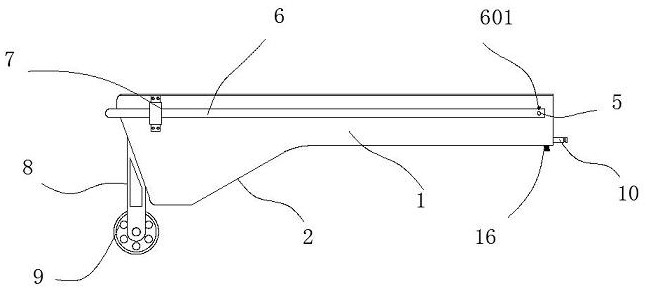
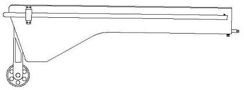
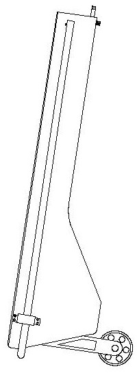
[0044] A waste collection device for CNC machine tools that is convenient for chip removal, comprising a tank body 1, a receiving part 2 is arranged on the left side of the tank body 1, and the depth of the receiving part 2 is greater than the depth of the tank body 1, When installing, the tank body 1 is inserted below the main shaft of the machine tool, and a partition 3 is arranged inside the tank body 1, and the right end of the partition board 3 is disconnected from the inner right side wall of the tank body 1, The front and rear sides of the tank body 1 are correspondingly provided with chute 101, and the chute 101 is arranged laterally. Inside the tank body 1, a scraper 4 is arranged above the partition plate 3. There is a rod 5 interspersed longitudinally inside the scraper 4, and the rod 5 and the scraper 4 are welded and fixed, and the rod 5 extends to the outside of the chute 101, and the rod 5 can be Sliding laterally along the chute 101 , the lower end of the scrap...

Embodiment 2

[0046] An upper baffle plate 12 is provided at the inner right side of the tank body 1, and the upper baffle plate has a material guide surface 13 inclined to the left and lower. When the scraper 4 moves to the right side to the extreme position, , located below the upper baffle 12; the function of the upper baffle 12 is to prevent chips from falling directly to the right side of the scraper 4 during machining.

Embodiment 3

[0048] The left end of the partition 3 is inclined and bent downward to form the first material guide surface 311; the first material guide surface 311 is inclined and then bent into the receiving part 2 to prevent chips from entering the partition 3 from the left side of the partition 3 below.


PUM


Abstract

The invention discloses a waste collection device for a numerically controlled machine tool which is convenient for chip removal, which comprises a tank body, a material receiving part is arranged on the left side of the tank body, and the depth of the material receiving part is greater than that of the tank body. During installation, the tank body is inserted below the main shaft of the machine tool, a partition is arranged inside the tank body, the right end of the partition board is disconnected from the inner right side wall of the tank body, and The front and rear sides are provided with chute correspondingly, the chute is arranged horizontally, and a scraper is arranged inside the trough above the partition; this product is convenient for collecting chips, and at the same time, it is convenient for cutting chips during processing. clean up.

Description

technical field [0001] The invention relates to a waste material collection device for a numerical control machine tool which is convenient for chip removal. Background technique [0002] The machine tool is an important tool for mechanical processing. During turning and grinding, a lot of chips will be generated. The chips entrain cutting fluid and fall into the waste tank, waiting for cleaning after the processing is completed. However, when we process a workpiece with a large feed rate, due to the large feed rate and long processing time, the amount of chips accumulated in the waste chute is relatively large, and it is very necessary to re-set the tool after stopping the operation. It is troublesome, and the procedure needs to go through again, which is very time-consuming, so the operator will risk opening the hatch to clean up, which has a greater safety hazard. [0003] For this reason, we have designed a waste collection device for CNC machine tools that is convenien...

Claims


Application Information

Patent Timeline
Patent Type & Authority Patents(China)
IPC IPC(8): B23Q11/00B23Q11/10
CPCB23Q11/0042B23Q11/0064B23Q11/1069
Inventor 熊秋艳郑晓
Owner 普锐米勒机床(东莞)有限公司
Why Eureka
Try Eureka