
Road grader front wheel auxiliary driving electro-hydraulic control system and road grader

An electro-hydraulic control system and auxiliary drive technology, applied in mechanically driven excavators/dredgers, earthmovers/shovels, construction, etc., can solve problems affecting construction efficiency, wheel slippage, etc., and improve construction efficiency , strong practicability, flexible control effect

Inactive Publication Date: 2020-09-18
XUZHOU XUGONG ROAD CONSTR MACHINERY
View PDF5 Cites 1 Cited by
  • Summary
  • Abstract
  • Description
  • Claims
  • Application Information

AI Technical Summary

Problems solved by technology

[0004] The purpose of the present invention is to provide an electro-hydraulic control system for the front wheel auxiliary drive of a grader and a grader, so as to solve the problem that in the prior art, when the foothold of the grader is poor, the wheels are prone to slipping, thereby affecting the construction efficiency. technical problem

Method used


Image

  • Road grader front wheel auxiliary driving electro-hydraulic control system and road grader

Examples


Embodiment 1

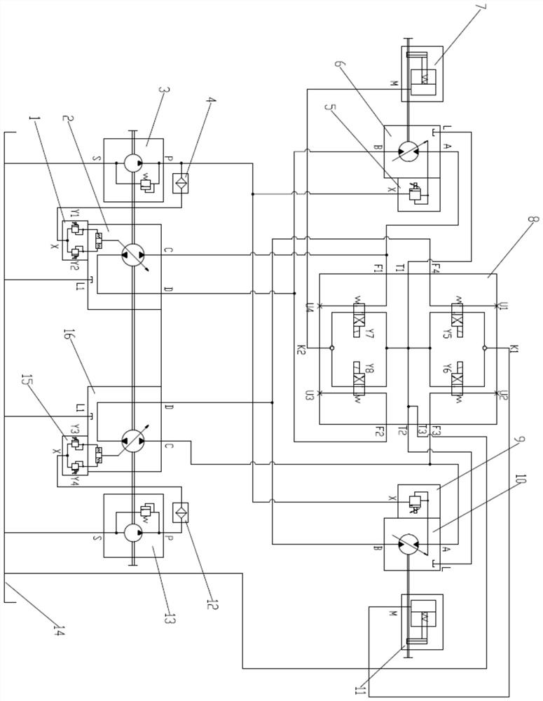
[0017] like figure 1 As shown, an electro-hydraulic control system for front wheel auxiliary drive of a motor grader, including a left front plunger pump control valve 1, a left front plunger pump 2, a left front charge oil pump 3, a left front filter 4, a left front motor control valve 5, and a left front motor 6 , left front reducer 7, front drive control valve 8, right front motor control valve 9, right front motor 10, right front reducer 11, right front filter 12, right front charge oil pump 13, hydraulic oil tank 14, right front plunger pump control valve 15 and right front column Plug pump 16 etc. parts. Through the connection of various components, the front wheel auxiliary drive hydraulic circuit is finally formed to provide driving force for the front wheels of the vehicle.

[0018] The S port of the left front charge pump 3 is connected to the hydraulic oil tank 14, and the P port is respectively connected to one end of the left front filter 4, the X port of the lef...

Embodiment 2

[0025] A motor grader. The front wheels of the motor grader described in this embodiment are equipped with the electro-hydraulic control system for the auxiliary drive of the motor grader front wheels described in Embodiment 1. The output shaft of the left front reducer 7 is connected to the left front wheel of the motor grader, and the right front The output shaft of speed reducer 11 connects the right front wheel of motor grader.

[0026]In the first working mode, the left front motor 6 drives the left front wheel of the grader through the left front reducer 7; the right front motor 10 drives the right front wheel of the grader through the right front reducer 11; the rear wheel of the grader is in neutral state; The machine as a whole is driven by two front wheels to achieve a two-wheel drive state. In the second working mode, the left front motor 6 drives the left front wheel of the grader through the left front reducer 7; the right front motor 10 drives the right front whe...


PUM


Abstract

The invention discloses a road grader front wheel auxiliary driving electro-hydraulic control system and a road grader, and belongs to the technical field of road graders. The road grader front wheelauxiliary driving electro-hydraulic control system and the road grader are used for solving the technical problem that in the prior art, due to the fact that the wheel slip phenomenon is prone to happen under the condition that the foothold of a road grader is quite bad, the construction efficiency is affected. The system comprises plunger pump control valves, plunger pumps, oil supplement pumps,filters, motors, motor control valves, speed reducers, a front driving control valve, a hydraulic oil tank and the like. By means of the connection of components, a front wheel auxiliary driving hydraulic circuit is finally formed, and the driving force is provided for wheel front wheels; and the driving wheel state and driving-wheel-free state are flexibly switched according to the actual usage environment, the road grader can have a two-wheel driving mode, a four-wheel driving mode and a six-wheel driving mode, the road grader wheel slip phenomenon is effectively improved under the conditionthat the foothold is quite bad, and the construction efficiency of the road grader is greatly improved.

Description

technical field [0001] The invention belongs to the technical field of graders, and in particular relates to an electro-hydraulic control system for front wheel auxiliary drive of the grader and the grader. Background technique [0002] Motor graders are mainly used for large-area ground leveling, trenching, slope scraping, bulldozing, loosening, snow removal and other operations such as roads and airports. Necessary engineering machinery. The motor grader generally adopts the structural form of rear wheel drive and front wheel steering. This structural form makes the road condition of the grader poor on the ground, and the six wheels are prone to wheel slippage when the foothold is poor, which affects the construction efficiency. It even caused the vehicle to be unable to construct. [0003] With the continuous improvement of human requirements for material life, machine operators have also put forward higher requirements for graders, requiring that the scope of use of gr...

Claims


Application Information

Patent Timeline
Patent Type & Authority Applications(China)
IPC IPC(8): E02F3/76E02F3/80E02F3/84E02F3/85
CPCE02F3/76E02F3/80E02F3/84
Inventor 范杨梁帮修张俊田瑞胡民政刘正亮
Owner XUZHOU XUGONG ROAD CONSTR MACHINERY
Learn More