
Method and device for reducing stray light

A technology of stray light and light source, which is applied in the field of optical color measurement, can solve the problems affecting the accuracy of energy detection and detection accuracy, and achieve the effects of reducing the difference between platforms, saving costs, and reducing the formation of stray light

Pending Publication Date: 2020-09-18
CHINA JILIANG UNIV
View PDF0 Cites 0 Cited by
  • Summary
  • Abstract
  • Description
  • Claims
  • Application Information

AI Technical Summary

Problems solved by technology

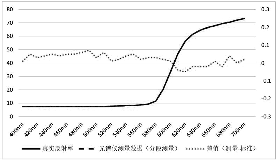
[0004] There is also a difference between the color value measured by the same spectral sensor from the surface of the tested sample and the real color value of the tested sample surface, which is called the indication error, and the key factor affecting the indication error is the stray light in the spectroscopic optical path. Astigmatism is specifically manifested as the light of a specific wavelength is not focused on the position of the array sensor when the specific wavelength is normally imaged, which affects the detection accuracy of the specific wavelength energy and also affects the detection accuracy of energy at other wavelengths.

Method used


Image

  • Method and device for reducing stray light
  • Method and device for reducing stray light
  • Method and device for reducing stray light

Examples


Embodiment 1

[0035] Divide the illumination light source into multiple segments within the measurement range for measurement (≥ 2 segments), add different optical filters 1 at the front end of the segmented light source 2, and measure in segments.

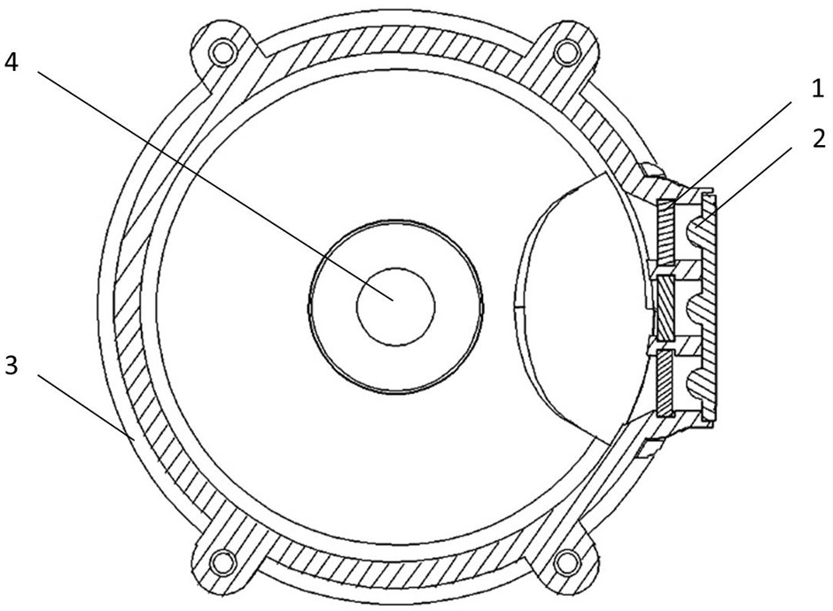
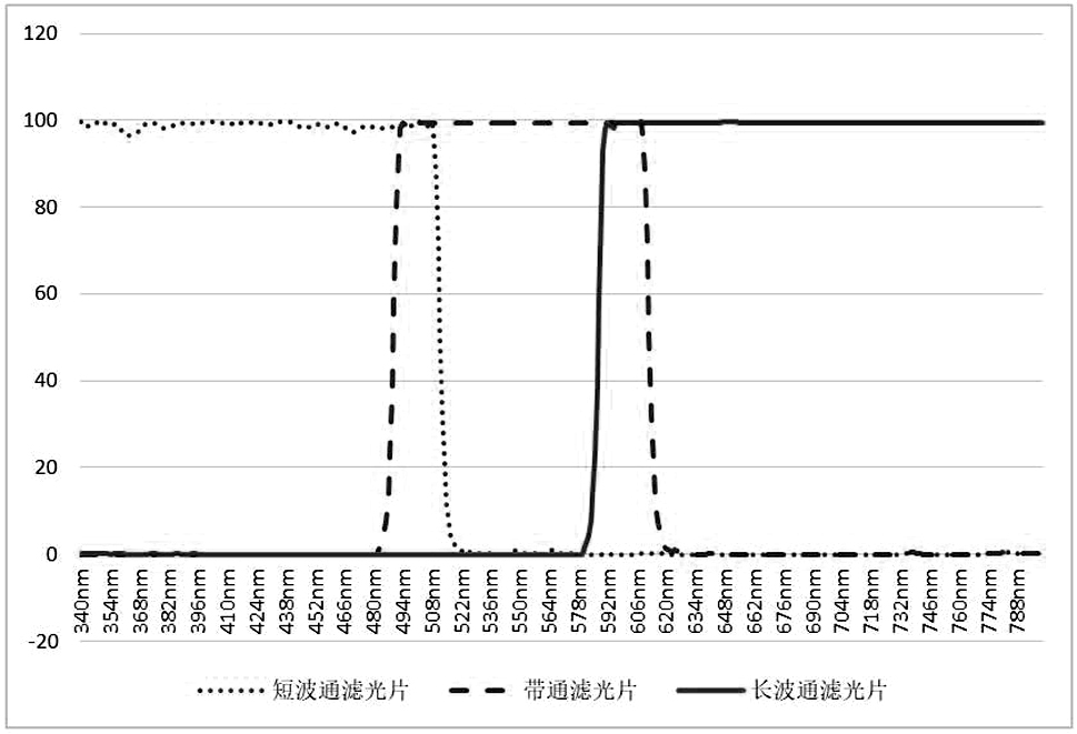
[0036] Take the three-segment measurement range as an example, such as Figure 1-3 As shown, select 3 groups of lighting LED lamps as the segmented light source 2 (full-spectrum LED, combined LED, halogen lamp, and xenon lamp can be used for this light source), among which, the first group of segmented light source 2 meets the spectral range of 360-510nm and has sufficient Spectral energy, the second group of segmented light sources 2 meets the spectral range of 490-610nm and has sufficient spectral energy, and the third group of segmented light sources 2 meets the requirement of 590-790nm and has sufficient spectral energy.

[0037] Add a short-wave pass filter 1 at the front end of the first group of segmented light sources 2, the working ran...

Embodiment 2

[0043]The lighting source uses a full-spectrum light source 7 within the measurement range (full-spectrum LED, combined LED, halogen lamp, xenon lamp, etc.), and the full-spectrum light source 7 irradiates the sample under test (or irradiates it through the measuring port 4 after being homogenized by the integrating sphere 3). The measured sample) is reflected to the spectral sensor 6, and multiple optical filters 1 (≥2 types) are added to the front end of the spectral sensor 6. The optical filter 1 is installed on the shutter 5, and the incident light of the spectral sensor 6 is switched by the movement of the shutter 5. The filter 1 at the front of the hole (it can also be a filter rotating wheel to switch the filter at the front of the spectral sensor 6).

[0044] Taking three kinds of filters as an example, such as Figure 2-4 As shown, 1. Shortwave pass filter 1, working range 360-510nm, cutoff range 510-800nm; 2. Bandpass filter 1, working range 490-610nm, cutoff range 3...


PUM


Abstract

The invention discloses a method and a device for reducing stray light. The method comprises the following steps of: S1, segmenting a measurement range; S2, selecting a group of optical filters in thecorresponding working range according to the segments of the measurement range, wherein the optical filters have cut-off ranges and are used for filtering spectral energy in other measurement ranges;S3, transmitting light to a sensor after filtering the light by means of the optical filters, measuring each segment of the measurement range by means of the sensor in sequence, and calculating to obtain reflectivity of the measurement range. The device comprises a light source, the optical filters and the sensor, wherein the group of optical filters with corresponding working ranges are arrangedin a matched mode according to the segments of the measurement range, the optical filters have cut-off ranges and are used for filtering spectral energy of other measurement ranges, and the optical filters are arranged between the light source and the sensor.

Description

technical field [0001] The invention relates to the technical field of optical color measurement, in particular to a method and device for reducing stray light. Background technique [0002] There are three main causes of stray light in the process of optical measurement: stray light generated by imaging optical path, stray light generated by non-imaging optical path and stray light generated by the instrument itself. [0003] The degree of stray light of different spectral sensors is different, resulting in differences in the color data measured by each sensor, which is called inter-station difference, and the stray light of each sensor needs to be measured and corrected. [0004] There is also a difference between the color value measured by the same spectral sensor from the surface of the tested sample and the real color value of the tested sample surface, which is called the indication error, and the key factor affecting the indication error is the stray light in the spe...

Claims


Application Information

Patent Timeline
IPC IPC(8): G01J3/02G01J3/46G01J3/28
CPCG01J3/0262G01J3/46G01J3/28
Inventor 袁琨贡双虎王坚陈涛曾亚澜方欣宇张宇梁章晓寅龚晓煜闫卓
Owner CHINA JILIANG UNIV
Learn More