

Progressive die stamping process equipment for lithium battery heat-conducting fin
A technology of stamping equipment and process equipment, which is applied in the field of continuous die stamping process equipment for thermal conductive sheets of lithium batteries, can solve the problems of difficulty in ensuring punching accuracy and waste of copper materials, and achieves improving punching accuracy, stability and stability. Effect
- Summary
- Abstract
- Description
- Claims
- Application Information
AI Technical Summary
Problems solved by technology
Method used
Image

Examples
Embodiment 1
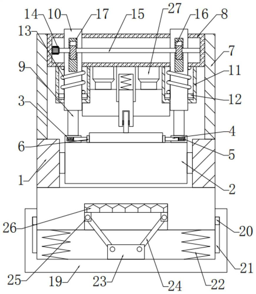
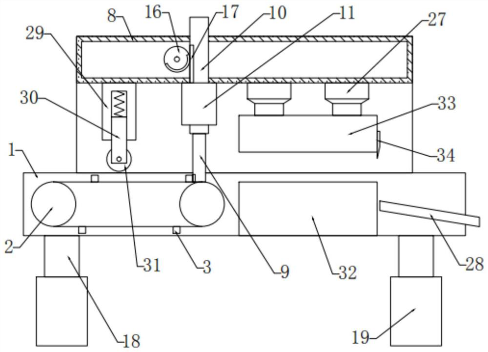
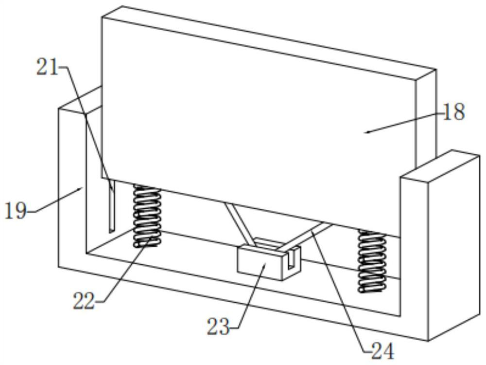
[0024] see Figure 1-3 , in an embodiment of the present invention, a lithium battery thermal sheet continuous die stamping process equipment, including a workbench 1, the inside of the workbench 1 is fixedly connected with a conveyor belt 2, and the right side of the conveyor belt 2 is provided with a stamping mechanism. The upper side of the conveyor belt 2 is provided with a positioning mechanism, and the bottom of the workbench 1 is provided with a shock-absorbing base.
Embodiment 2
[0026] In this embodiment, the positioning mechanism includes a support plate 7 fixedly connected to the top of the left and right ends of the workbench 1, a top plate 8 is fixedly connected between the support plates 7 on both sides, and the inner side of the top plate 8 is bolted. There is a motor 14, the output end of the motor 14 is connected to the rotating rod 15, and the outer sides of the left and right ends of the rotating rod 15 are fixedly connected with an incomplete gear 16, and the rear side of the incomplete gear 16 is provided with a sliding connection with the top plate 8 The slide plate 10, the outer side of the slide plate 10 is fixedly connected with a rack 17 meshed with the incomplete gear 16, and the outside of the bottom end of the slide plate 10 is provided with a fixed block 11 fixedly connected with the top plate 8, and the outside of the slide plate 10 is fixed. A connection block 12 is provided for sliding connection with the fixed block 11, a secon...
PUM
 Abstract
Description
Claims
Application Information